Removal and replacement procedures 33
2.
Place the server on its side.
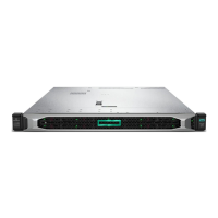
3. Remove the feet.
To replace the component, slide it back into the locking slot. Be sure that the foot clicks securely into the
chassis. Repeat with the remaining feet, as necessary.
Tower configuration panels
To remove the component:
1. Power down the server (on page 29).
2. Remove the tower feet (on page 32).
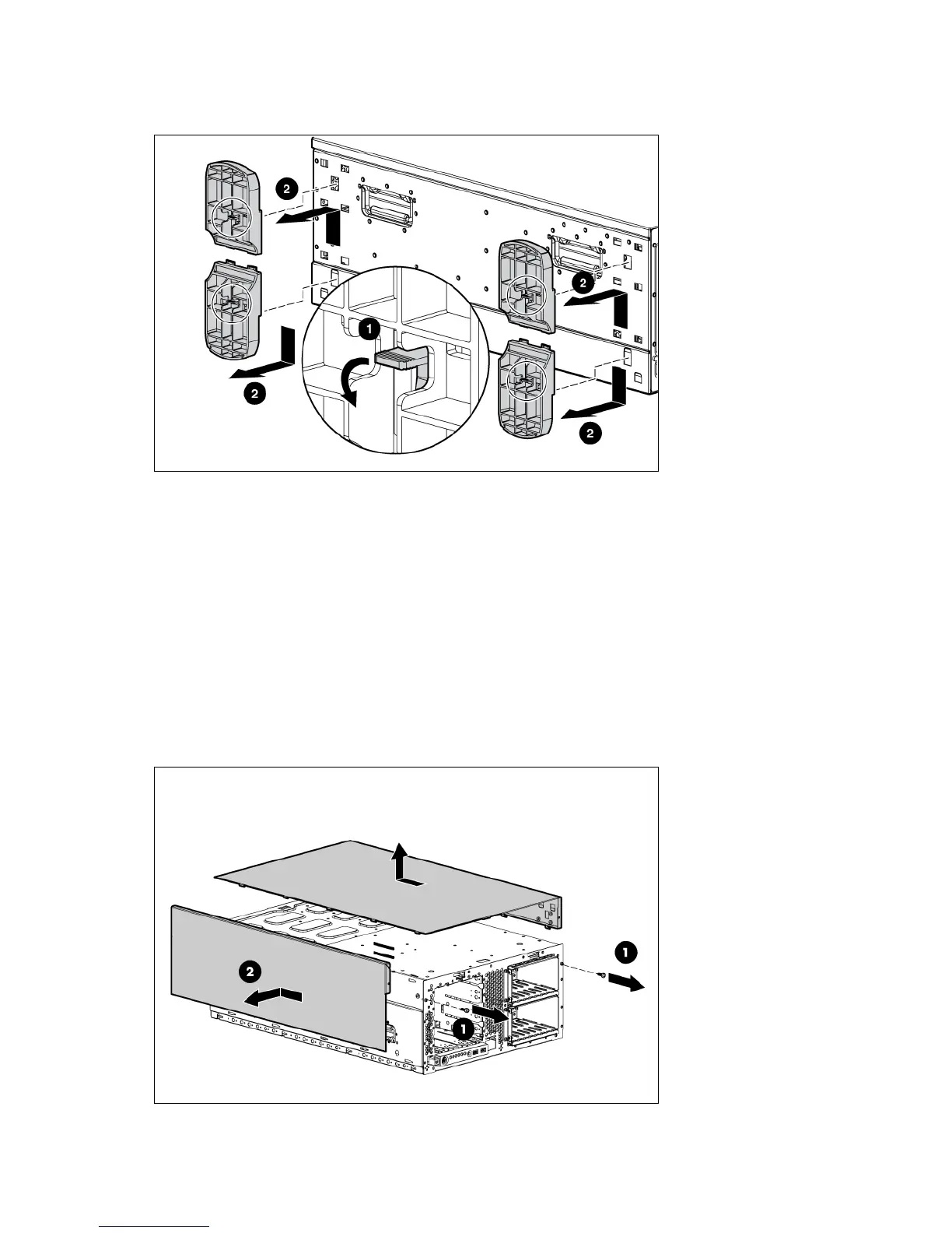
3. Remove the tower configuration panels:
a. Use the T-10/T-15 Torx screwdriver to remove the two front panel screws.
b. Remove the tower configuration panels.
 Loading...