Server component identification 83
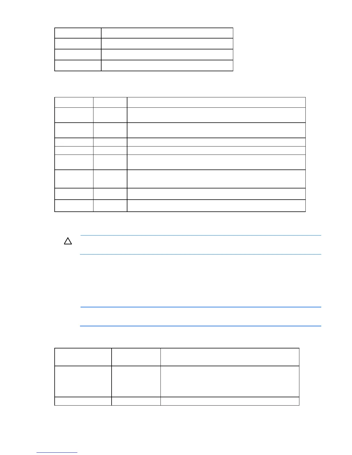
Item Description
25
Serial 2 connector
26
Parallel connector
27
Diskette drive connector
System maintenance switch
Position Default Function
S1
Off Off = iLO 2 security is enabled.
On = iLO 2 security is disabled.
S2
Off Off = System configuration can be modified.
On = System configuration is locked and cannot be modified.
S3
Off Reserved
S4
Off Reserved
S5
Off Off = Power-on password is enabled.
On = Power-on password is disabled.
S6
Off Off = Normal
On = ROM treats system configuration as invalid.
S7
Off Reserved
S8
Off Reserved
When the system maintenance switch position 6 is set to the On position, the system is prepared to erase all
system configuration settings from both CMOS and NVRAM.
CAUTION: Clearing CMOS and/or NVRAM deletes configuration information. Be sure to
properly configure the server or data loss could occur.
Internal system health LED combinations
When the internal system health LED on the front panel ("Front panel LEDs and buttons" on page 79)
illuminates either amber or red, the server is experiencing a health event. Combinations of illuminated HP
Systems Insight Display LEDs and the internal health LED indicate system status.
NOTE: The system management driver must be installed for the internal system health LED to
provide pre-failure and warranty conditions.
The front panel health LEDs indicate only the current hardware status. In some situations, HP SIM may report
server status differently than the health LEDs because the software tracks more system attributes.
HP Systems Insight
Display LED color
Internal system
health LED color
Status
Processor failure,
socket X (amber)
Red One or more of the following conditions may exist:
Processor in socket X has failed.
Processor X is not installed in the socket.
ROM detected a failed processor during POST.
Amber Processor in socket X is in a pre-failure condition.
 Loading...