EL-MF877-00 Page 2
Template Revision B
PSG instructions for this template are available at EL-MF877-01
List the type and size of the tools that would typically be used to disassemble the product to a point where components
and materials requiring selective treatment can be removed.
Tool Size (if
applicable)
Description #1 Phillips screwdriver (for 12 PCS on bottom case )
Description #2 Phillips screwdriver (for 9 PCS on motherboard)
Description #3 Phillips screwdriver (for 2 PCS on HDD Bracket & 4 PCS on Battery)
Description #4 Phillips screwdriver (for 10 PCS on base side hinge bracket)
Description #5 Use jig disassembly Lcd Bezel with Lcd cover
thickness
3.0 Product Disassembly Process
3.1 List the basic steps that should typically be followed to remove components and materials requiring selective treatment:
1. Release 4 Phillips #2 screws then remove roof cover by hands from top side refer figure 1
2. Release 2 Phillips #2 screws then push out ODD kits. refer figure 2
3. Check hood sensor cable would be remove from hook of FAN. refer figure 3
4. Release 3 T15 screws then remove FAN from system.
5. Release 4 T15 screws then remove heat sink refer figure 4
6. Unplug Power FFC, Speaker cable and CCD cable refer figure 5
7. Unplug LVDS FFC cable refer figure 6
8. Unplug Antenna cable, Back light cable, Hood sensor cable, HDD FFC cable, Touch cable., Touch cable. Don’t unplug
RTC battery
9. Release 1 Phillips #1 screw then remove Wireless card refer figure 9
10. Move outward the latch on both side of the DIMM.Then take out DIMM refer figure 10
11. Release 3 T15 screws to take out MB refer figure 11
12. make the system turn the other side.Remove the speaker grill by hands refer figure 12
13. Release 4 T15 screws then remove speaker refer figure 13.
14. Remove Power holder with releasing 1 Phillips #1 screw refer figure 14.
15. Remove 2 antenna from plastic refer figure 15
16. Release 3 Phillips #1 screw then make system turn to other side refer figure 16
17. Remove webcam housing cover by hands refer figure 17
18. Release 2 Phillips screws then remove CCD bracket.Unplug the webcam cable.refer figure 18
19. Release 4 Phillips screws then take out the pop up webcam structure refer figure 19
20. Release 2 Phillips screws then remove CCD bracket. Unplug the webcam cable. refer figure 20
21. Release 4 Phillips #1 screws then remove basepan bracket. You will see LVDS and back light cable refer figure 21
22. Remove 6 Phillips #1 screws can make the LCD and panel frame to be separated refer figure 22
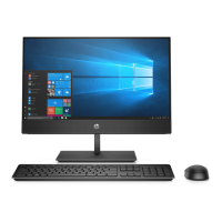
3.2 Optional Graphic. If the disassembly process is complex, insert a graphic illustration below to identify the items
contained in the product that require selective treatment (with descriptions and arrows identifying locations).
 Loading...

