List the type and size of the tools that would typically be used to disassemble the product to a point where components
and materials requiring selective treatment can be removed.
Tool Size (if
applicable)
Description T15 screw driver (Disassemble 3 pcs screws for ODD bkt and main bkt)
Description T15 screw driver (Disassemble 4 pcs screws for Fio module and main bkt)
Description T15 screw driver (Disassemble 4 pcs screws for MB and main bkt)
Description T15 screw driver (Disassemble 4 pcs screws for PSU and main bkt)
3.0 Product Disassembly Process
3.1 List the basic steps that should typically be followed to remove components and materials requiring selective treatment:
1. Remove to lower case from hosing.
2. Pull off ODD SATA con &ODD power con.
3. Remove ODD and Front Bezel from hosing
4. Loosen 3 screws on main brkt then remove ODD cage.
5. Pull off all cables on MB.
6. Loosen 4 screws on main brkt then remove FIO module.
7. Loosen 4 screws on MB then remove it.
8. Loosen 4 screws on PSU then remove it.
9.
10.
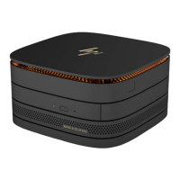
3.2 Optional Graphic. If the disassembly process is complex, insert a graphic illustration below to identify the items
contained in the product that require selective treatment (with descriptions and arrows identifying locations).
1.Remove to lower case from hosing.