Page 5 of 8
The Hire Supply Company (UK) Limited
Assembly instruction and any other consideration for the safe set-up of the product.
Remove packaging used to secure product in transit including any materials to protect the cooling pads
Attach castors to the bottom of the unit. For the BCE45LV2 the castors attach directly onto the base
moulding. For the BCE60LV2 the castors are affixed to a moulded castor bracket, connect these brackets
directly onto the base.
The following tools will be required to complete the assembly requirements - PZ2 – pozi-drive screwdriver
Choose either of the following two methods to fill the unit with water:
A. Automatic - Attach a ½” hose connector to the fill inlet on the equipment.
B. Manual – Open the water inlet door and fill.
ALWAYS ENSURE THE EVAPORATIVE AIR COOLER IS UNPLUGGED WHILST FILLING WITH WATER.
DO NOT EXCEED THE MAXIMUM WATER LEVEL SHOWN ON THE WATER LEVEL DISPLAY
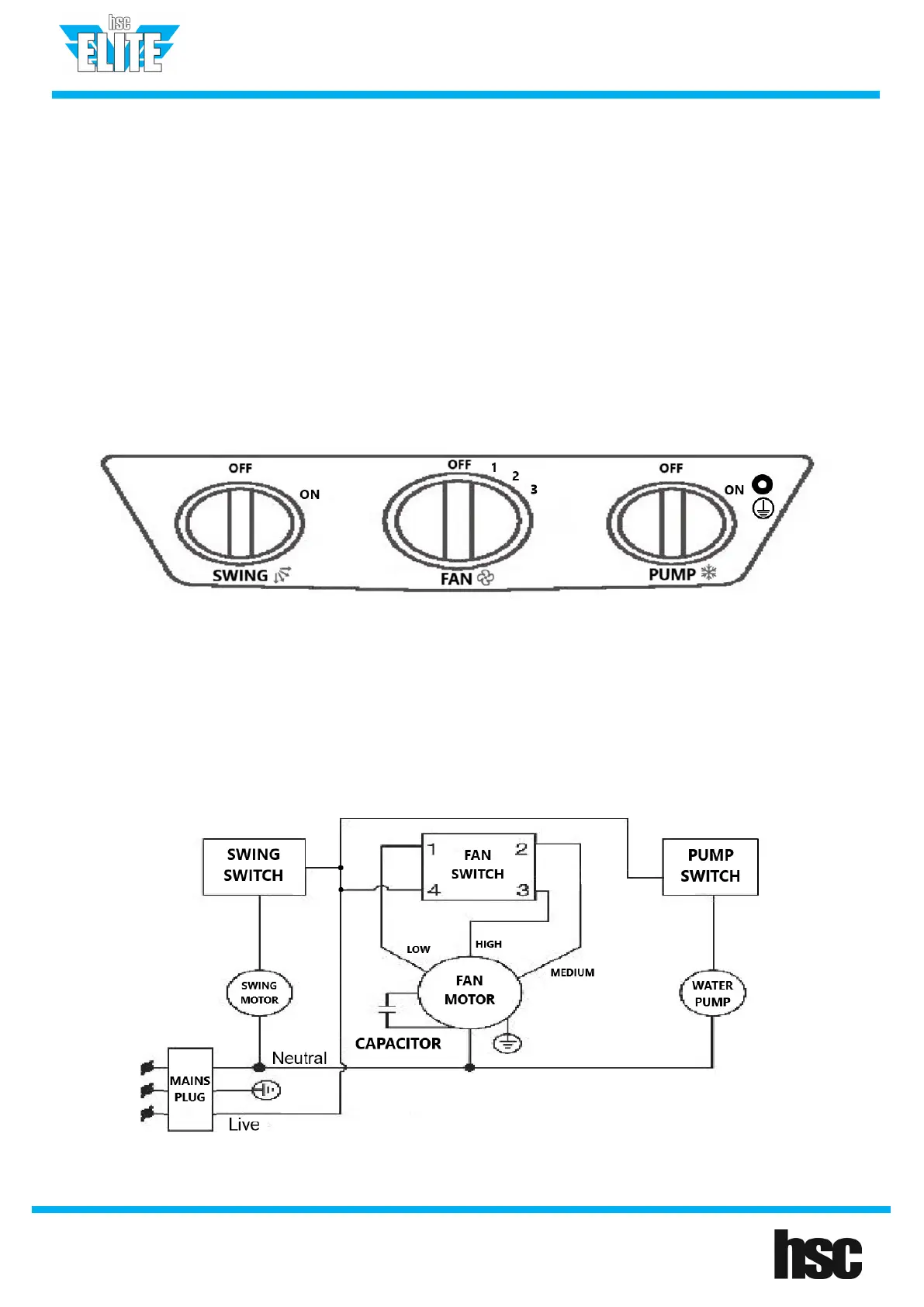
• Turn the equipment on by turning the “FAN” switch dial to either LOW or HIGH
1. SWING: Controls the swing function to direct the air over a greater area.
2. FAN: Turn clockwise to control the speed of the fan. There are 3 speed setting, LOW, MEDIUM, and HIGH
NOTE: The Elite Evaporative Air Cooler can be used in fan only mode without water
3. PUMP: Once in the on position the water will start to recirculate and give the unit the cooling function
NOTE: There is a dedicated earth point clearly identified on the control panel for Class I earth continuity
testing.