LP-387 Rev. 7.3.15
11
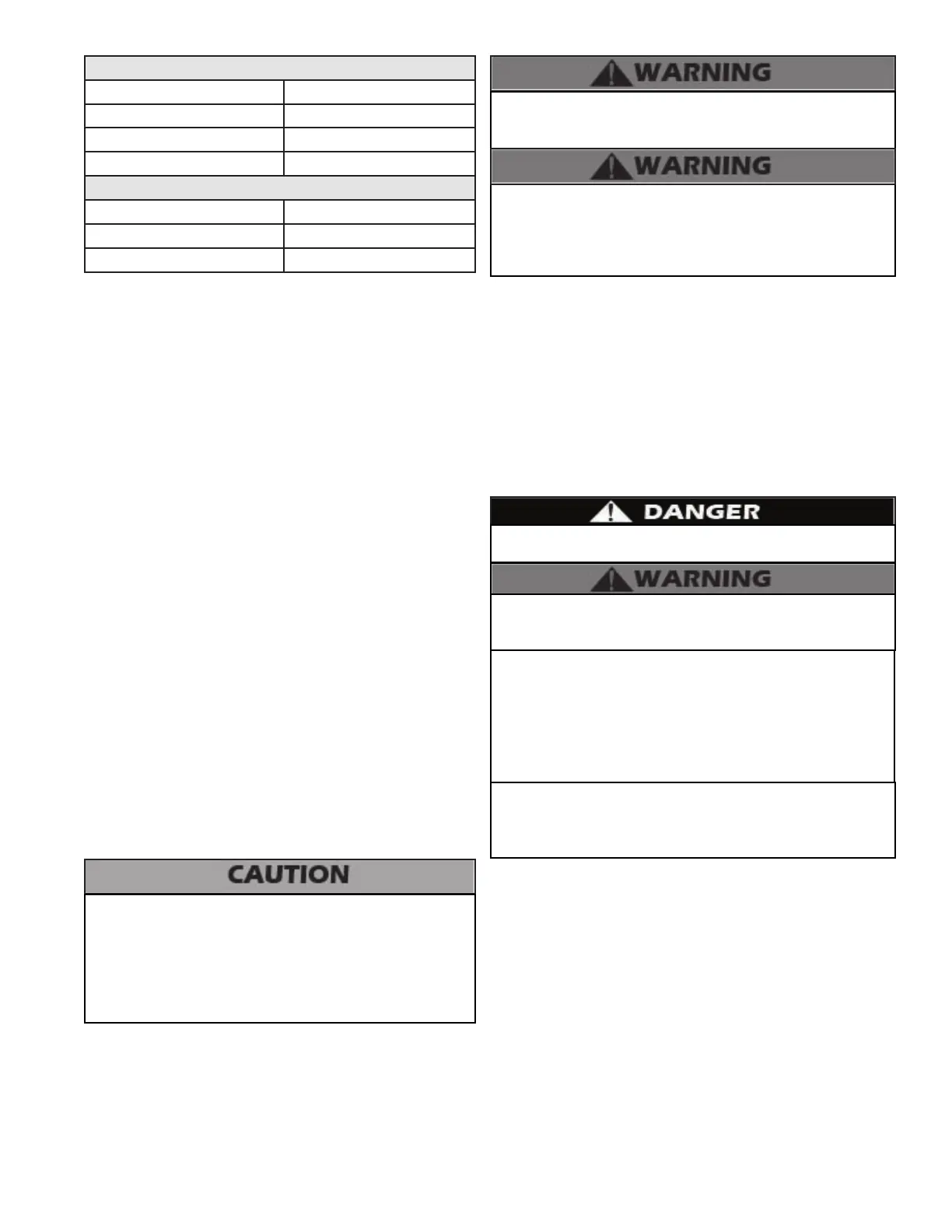
Required Amount of Bolts for Wall-Mounting the Boiler
Model Amount of Bolts
EFT-55 - 110 2
EFT-155 - 285 4
EFT-399 6
Pilot Hole Size by Wood Type
Type Drill Bit Size
Soft 3/32”
Hard 3/16”
Table 1 - Bolts Required and Pilot Hole Size for Wall-Mounting
the EFT Boiler
G. Residential Garage, Closet, and Alcove Installations
Precautions
If the boiler is located in a residential garage, per ANSI Z223.1:
• Install the boiler burner and ignition devices a mini-
mum of 18” above the oor of the garage. This will
ensure the burner and ignition devices are well o the
oor.
• Locate or protect the boiler so it cannot be damaged
by a moving vehicle.
Check with your local Authority Having Jurisdiction for
requirements when installing boiler in a garage, closet, or
alcove. Please read the entire manual before attempting
installation. Failure to properly take factors such as boiler
venting, piping, condensate removal, and wiring into account
before installation could result in wasted time, money, and
possible property damage and personal injury.
For closet or alcove installations, a two pipe venting system
must be used. Failure to follow this warning could result in
substantial property damage, severe personal injury, or death.
2. Mounting to a Metal Frame
a. The provided mounting bracket must be mounted to the
center of at least 2 studs using standard steel or stainless
steel toggle bolts 3/16” diameter or larger, and at least 2”
long for direct mounting on stud for EFT-55 – 110 models,
and 3/8” diameter or larger, and at least 2” long for EFT-155
– 399 models for direct mounting on at least 18 gauge studs.
Be sure the bracket is level and mark the hole location of the
top bracket height and horizontal stud location. Ensure the
marked holes are located in the center of the building frame
(studs).
b. 2” is the minimum toggle bolt length if the bracket is directly
on stud. Increase length for any materials covering the studs.
c. Predrill holes on the marked stud locations. The predrilled
holes should be ½” in diameter for 3/16” bolts, and ¾” in
diameter for 3/8” bolts, to allow for the collapsed wings of the
toggle to slide through. Ensure that the predrilled holes are
straight and square to the wall. Failure to do so could lead to
insucient support of out of level boiler. See Figure 4.
d. Using the predrilled holes, mount the hanger bracket to the
building frame (studs) with the toggle bolts. Ensure that the
bolt toggles are through the stud and expanded catching the
inside of the stud. Tighten the toggle bolt until the mounting
bracket is secure. Hang boiler on the now wall mounted
bracket. Be certain that the bracket is engaged before letting
the boiler hang free. Slowly release the weight of the boiler
while ensuring the bracket is properly secure. Verify that the
boiler is securely mounted before leaving it unsupervised.
H. Exhaust Vent and Intake Pipe
The boiler is rated ANSI Z21.13 Category IV (pressurized vent,
likely to form condensate in the vent) and requires a special vent
system designed for pressurized venting.
NOTE: The venting options described here (and further
detailed in the Venting section, this manual) are the lone
venting options approved for this boiler. Failure to vent the
boiler in accordance with the provided venting instructions
will void the warranty.
NOTE: For installations using room air for combustion, refer to
the boiler venting section, this manual.
The space must be provided with correctly sized combustion/
ventilation air openings for all other boilers located in the space
with the boiler. Do not install the boiler in an attic. Failure to
comply with these warnings could result in substantial property
damage, severe personal injury, or death.
Failure to vent the boiler properly will result in serious personal
injury or death.
Do not attempt to vent this boiler by any means other than
those described in this manual. Doing so will void the warranty
and may result in severe personal injury or death.
Vents must be properly supported. Boiler exhaust and intake
connections are not designed to carry heavy weight. Vent
support brackets must be within 1’ of the boiler and the balance
at 4’ intervals. Boiler must be readily accessible for visual
inspection for rst 3’ from the boiler. Failure to properly support
vents could result in property damage, severe personal injury,
or death.
The exhaust discharged by this boiler may be very hot. Avoid
touching or other direct contact with the exhaust gases of the
vent termination assembly. Doing so could result in severe
personal injury or death.
1. Direct Vent of Exhaust and Intake
If installing a direct vent option, combustion air must be drawn
from the outdoors directly into the boiler intake and exhaust
must terminate outdoors. There are three basic direct vent
options detailed in this manual: 1. Side Wall Venting, 2. Roof
Venting, and 3. Unbalanced Venting.
Be sure to locate the boiler such that the exhaust vent and
intake piping can be routed through the building and properly
terminated. Dierent vent terminals can be used to simplify and
eliminate multiple penetrations in the building structure (see
Optional Equipment in Venting Section). The exhaust vent and
intake piping lengths, routing, and termination methods must
all comply with the methods and limits given in the Venting
Section, this manual.
When installing a combustion air intake from outdoors, care
must be taken to utilize uncontaminated combustion air. To
prevent combustion air contamination, see Table 2.
 Loading...