43
LP- 205 REV. 9.2.14
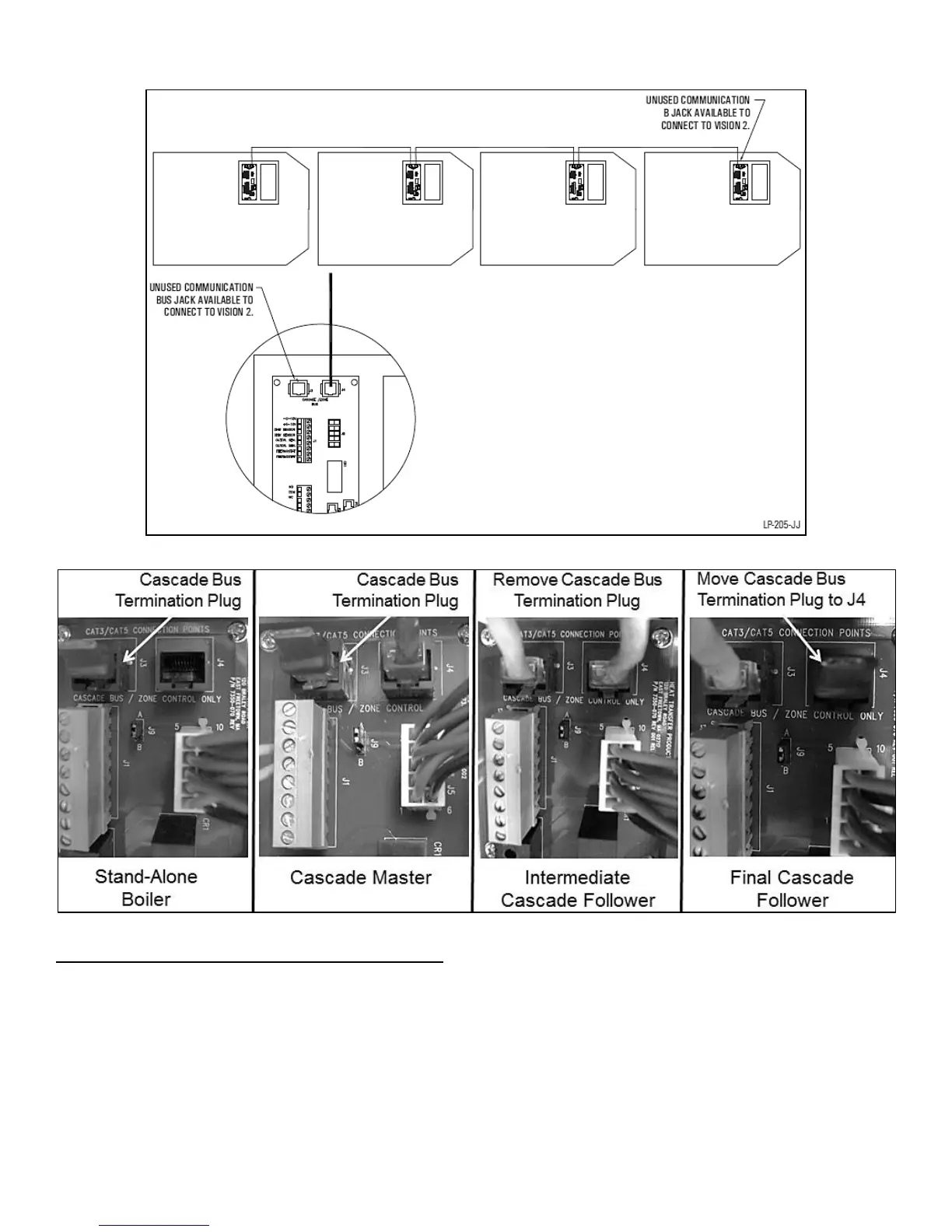
Figure 24
Figure 25 – Cascade Resistor Plug Installation Detail
O. CASCADE MASTER PUMP AND SENSOR WIRING
1. Place the cascade master overlay sticker onto the field connection board on the boiler designated as the cascade master.
2. Connect the system pump hot wire to the terminal marked SYS PUMP.
3. Connect the system pump neutral to the BOILER NEUT terminal and the pump ground wire to the BOILER GND terminal.
4. Connect a jumper wire from the 120 VOLT terminal to the SYS PUMP PWR terminal.
5. Connect the boiler pump to the terminals marked BOILER HOT, BOILER NEUT, and BOILER GND.
6. Connect the system pipe sensor to the terminals marked SYS SENSOR.