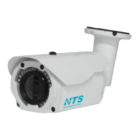
The HTS VRS N70 Imaging Unit is a 2-megapixel network camera series designed for various imaging applications, offering a robust set of features for both functionality and ease of use. This quick installation guide provides essential information for setting up and maintaining the device.
Function Description
The N70 Imaging Unit is a state-of-the-art, 2-megapixel imaging unit that provides real-time video images over the Internet and an Intranet. It is supplied with a 2-shielded copper pair for power and I/O, and an Ethernet interface for transmission of images. The Ethernet interface is also used by management software to configure the imaging unit and provide power via PoE+. The unit is designed to be connected to a Lane Controller (LC-2000 or similar) for network connectivity, supporting up to 8 imaging units per controller. The device also features motorized focus and zoom functions, which are managed using the Controller Application from HTS. Live video viewing and lens sub-window controls (Zoom In, Zoom Out, Focus Near, Focus Far) are available for precise image adjustment.
Important Technical Specifications
- Sensor Type: 1/2.8" SONY STARVIS CMOS
- Active Pixels: 1945 x 1097 @30 fps
- Lens: Digital Zoom x16
- Effective Range: Standard: 3-17 meters
- Angle of View: 54.0° (H) ~ 4.9° (V)
- Video Compression: H.264
- Protocol: TCP/IP
- Housing – Mechanical / Electrical:
- Weight: 1.2 Kg
- Protection Level: Water/Dust proof IP66, Vandal IK10
- Operating Temperature Range: -30°C ~ 50°C / -20°F~122°F
- Adjustment Angles: 3 (up/down, right/left, Yaw)
- Line In: 12VDC (19.2W), PoE+ (23W)
- Heating: Contains heater with thermostat control
- Illumination:
- Spectrum: Infra-red (850nm or 730nm), or white illumination
- Quantity: 32 LEDs
- Safety and Certifications:
- CE Regulation: Yes
- Manufacturing Quality Certification: ISO 9001-2008
- Unit Dimensions: 288.5 mm (length) x 98.4 mm (width) x 92.9 mm (height), with a diameter of 68.0 mm and a mounting hole diameter of 80.0 mm.
- Connectors:
- P5 (RJ-45): Ethernet, RJ-45 10/100Mbps, PoE+
- P6 (DC Jack): Main Power, DC12V Input
- P7 (Alarm_Out): Alarm_output terminal, 3 pin terminal (Normally_Closed, Common, Normally_Open)
- P8 (MIC (Audio In)): Audio line input, 2 pin terminal (MIC (Audio In), G (GND))
- P9 (SPK (Audio Out)): Audio line output, 2 pin terminal (SPK (Audio Out), G (GND))
- P10 (Alarm_In): Alarm input terminal, 2 pin terminal (AI-P, N)
Usage Features
The N70 Imaging Unit is designed for straightforward installation and configuration.
- Installation Tools: Requires an electric drill, screwdrivers, wire cutters, and a set of hex keys (Allen wrenches).
- Mounting Options:
- Wall Mounting: The unit can be mounted on a wall using screws. It is recommended to attach the sun shade to the unit first, then place the unit on the wall using two screws in the plastic bag. A placement sticker is provided to mark drilling locations. Cables can be routed in two different ways (cable position method 1 and method 2) to suit installation needs. Finally, the unit is secured with three self-tapping screws.
- Pole Mounting: For pole mounting, a pole mount adaptor kit is supplied. The sun shade is connected, and two metal bands are inserted into the pole mount adaptor. A screw driver is used to fasten the metal bands around the pole. The unit is then placed in position and fastened with three screws to the pole mount adaptor.
- Adjusting the Imaging Unit Position: An L key is supplied to adjust the axis screws, allowing for 360° rotation and 90° tilt for optimal camera positioning. After completing adjustments, all screws should be tightened to prevent the imaging unit from moving.
- Network Configuration:
- Direct Connectivity: The N70 unit connects to a Lane Controller (LC-2000 or similar) via its Ethernet RJ-45 network interface. Up to 8 imaging units can be connected to a single Lane Controller.
- Switch Connectivity: Alternatively, the units can be connected to a switch, which then connects to the Lane Controller.
- IP Configuration: The unit has a network-based default IP address (192.168.0.30) and subnet mask (255.255.255.0). An IP Configurator Utility is provided to locate the imaging unit in the local area network. This utility can be run from the Lane Controller (LC-2100 or LC-2000) or downloaded from the HTS website.
- Setting a New IP Address: To set a new IP address, the imaging unit and Lane Controller must be in the same subnet. The N70 Eth connector connects directly to the Lane Controller or via a switch. The IP configurator displays a login window (user name: admin, password: ****). After logging in, a list of units on the network is displayed. The desired unit (N70) is selected, and its configuration window appears. A new IP address can be entered in the designated field, and "Save" is clicked to activate the settings. The imaging unit reboots with the new IP address.
- Setting Focus and Zoom: Motorized focus and zoom functions are managed via the Controller Application from HTS. The Live Video Viewer/Lens sub-window allows control of Zoom In, Zoom Out, Focus Near, and Focus Far. Refer to the "Controller Application User's Manual" – "Live Video Viewer" chapter for configuring real-time video stream options.
Maintenance Features
- Safety Instructions:
- The unit operates at 12VDC and uses PoE+.
- Installation and service should be performed by qualified and experienced technicians.
- Clean the imaging unit with a dry soft cloth; for tough stains, use a small quantity of diluted neutral detergent and wipe dry with a soft cloth.
- Do not apply benzene, gasoline, or thinner to the imaging unit, as it may melt the surface or cause fogging in the lens.
- Avoid aligning the lens to very bright objects (e.g., light fixtures) for long periods.
- Operating and storing the unit in the following locations:
- Extremely humid, dusty, or hot/cold environments (recommended operating temperature: -30°C to +50°C).
- Close to sources of powerful radio or TV transmitters.
- Close to fluorescent lamps or objects with reflections.
- Under unstable or flickering light sources.
- For eye safety – avoid looking directly to the LED’s illumination beam.
- Disposal of Equipment: The WEEE (Waste Electrical and Electronic Equipment) symbol indicates that this product should not be disposed of with unsorted municipal waste. Correct disposal is applicable in the European Union and other European countries with separate collection systems, in accordance with local laws, regulations, and procedures.
- Checking for Damage: Upon first unpacking, check for any visible damage to the unit and its accessories. Protective materials used for packaging should be able to protect the unit from damage during transportation. Contact HTS if any items are damaged or missing.
- Unpacking the Unit: The N70 package includes: One N70 imaging Unit, one printed Quick Installation Guide (this document), and one sunshield.
- Mounting Accessory Kit: Includes 1 secure screw M5x8mm/ SUS/ Black (item 4), 3 screws (M4x15) for mounting bracket (item 1), 1 plastic washer (item 5), and 1 wrench 3mm tool (L key) (item 2).
- Power Supply: A warning indicates that to avoid damage to the unit, it should only be connected to the original supplied power supply.
- IP Address Recall: In order to recall the imaging unit’s IP address when necessary, stick a label with the IP address on the imaging unit.