15
Installing the AP
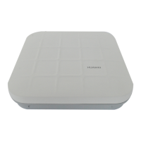
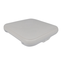
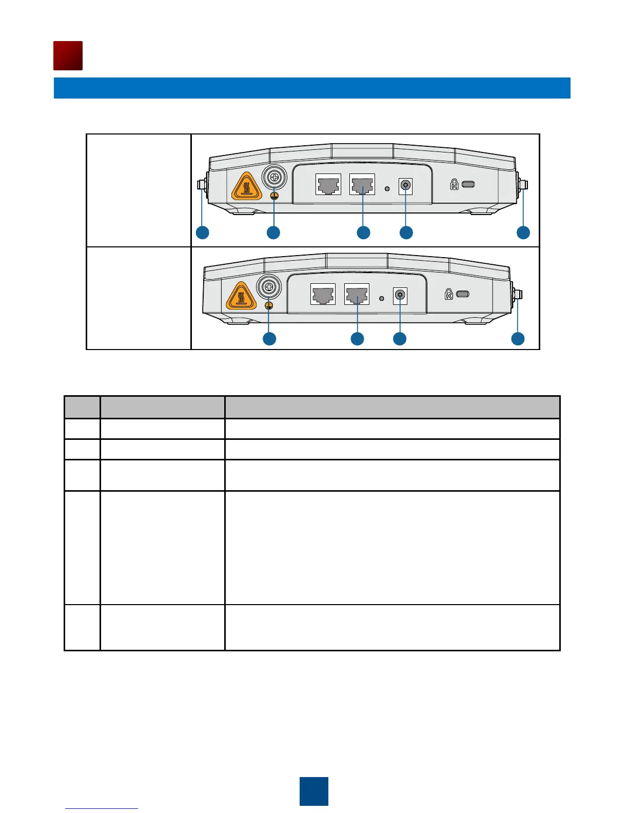
Table 6 Appearance of indoor APs (front view)
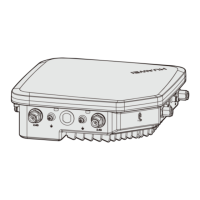
1
Console
2 3 4 5
ETH/PoE Default
DC 12V
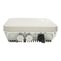
3 4 5 2
Console ETH/PoE Default
DC 12V
Connects to the 5 GHz antenna for transmitting and receiving signals.
Connects to the 2.4 GHz antenna for transmitting and receiving signals.
Connects to the ground cable, with the M4 end connected to the ground
cable and M6 end connected to the protection ground.
• The network cables used are category-5 twisted pairs.
• If the AP needs to connect to the Ethernet, ensure that the
Ethernet cable is working properly. If the Ethernet cable is not
working properly, for example, RJ45 connectors are short-
circuited, the AP may fail to be powered on or fail to work. Before
connecting an Ethernet cable to the AP, use the cable test tool to
check whether the cable is qualified. If the cable is unqualified,
replace it.
• The AP supports PoE power supply and DC power supply.
• Use the power adapter attached with the AP; otherwise, the AP
maybe damaged.
Table 7 Cables of indoor APs
Requirements for making a network cable:
Cut the cable of proper length based on the distance between the AP and the PSE device, peel
the insulation on both ends of the network cable, and crimp the wires to RJ45 connectors.
Connect RT45 connectors to the network cable tester to test cable connectivity. The following
shows the pin assignment.
 Loading...