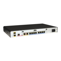
Figure 2-14 AR2240 rear view
1: Pluggable card
2: ESD jack 3: Ground screw 4: AC jack
6: Pluggable AC
power supply unit
8: Pluggable fan
module
9: SRU 10: AC power switch
13: Two Fixed GE
interfaces on the panel
14: Mini USB interface 15: CON/AUX
interface
16: Micro SD card
interface
17: GE optical/
electrical Combo
interface
18: USB interfaces
NOTE
After a 3G USB modem
is inserted, install a
protection cap on it, as
shown in the following
figure.
NOTE
The two power supply units of the AR2240 work in load balancing mode.
Slot Distribution
Figure 2-15 shows slot distribution on AR2200.
NOTE
l Two SIC slots can be combined into one WSIC slot by removing the guide rail.
l Two SIC slots and one WSIC slot can be combined into one XSIC slot by removing the guide rail.
l Two XSIC slots can be combined into one EXSIC slot by removing the guide rail.
l Slots can be combined into one, but one slot cannot be divided into multiple slots.
l After two slots are combined into one, the slot ID is the larger number of the two original slots.
l In AR V200R002C00, a WSIC card can be inserted into an XSIC slot with a special component. The
WSIC card is in the lower side of the slot and uses the XSIC slot ID as its own slot ID.
Huawei AR1200&2200&3200 Series Enterprise Routers
Hardware Description 2 Chassis
Issue 03 (2012-04-20) Huawei Proprietary and Confidential
Copyright © Huawei Technologies Co., Ltd.
23

 Loading...


