You can use a flat-head screwdriver to install floating nuts.
NOTE
4
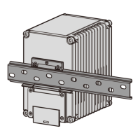
Mount the router on the vertical rack-mounting bracket.
a. Use a Phillips screwdriver to remove the seven M4 screws at the back of the router.
b. Align the seven M4 mounting holes on the vertical rack-mounting bracket with those at the back of the
router.
c. Use M4 screws to fix the router on the vertical rack-mounting bracket.
Move the router and vertical rack-mounting bracket into the cabinet. Use the Phillips screwdriver to tighten
the M6 screws on a diagonal line on the vertical rack-mounting bracket, and then tighten the M6 screws
on the other diagonal line.
Step 2
Step 3
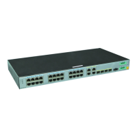
1
4
3
SYS
USB
SYNC
PoE1
PoE2
DC1
DC2
0
1
2
3
4
5
6
7
8
9
10
11
0
1
16
17
12
13
14
15
RE
SET
CONSOLE
G
E
10
G
E
GE/PoE+
48
V; 5
A
1
2
V-48V;
6
A
2
.5
G
E
- +
DI
- +
PoE2
- +
PoE1
- +
DC2
- +
DC1
6 Connecting the Router
Do not connect cables while the power is on.
Do not power on the router before you finish connecting and routing cables.
Invisible laser beams will cause eye damage. Do not look into bores of optical modules or connectors of
optical fibers without eye protection.
For details about pin assignments and cable connections, see the Hardware Description.
Before You Start
2.a
2.c
 Loading...