The DTSU666-HW Smart Power Sensor is a device designed for precise measurement and monitoring of electrical parameters in various power grid systems. It serves as a crucial component for energy management, offering detailed insights into power consumption and generation.
Function Description
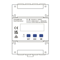
The DTSU666-HW primarily functions as a smart power sensor, capable of measuring voltage, current, active energy, and power factor. It supports both direct connection for currents up to 80 A and connection through current transformers (CTs) for higher currents (greater than 80 A), making it versatile for different load requirements. For voltage measurement, it can be directly connected for line voltages up to 500 V, and requires potential transformers (PTs) for voltages exceeding 500 V.
The device is compatible with both three-phase four-wire and three-phase three-wire power grid systems, allowing for flexible integration into various electrical infrastructures. It includes RS485 communication ports (terminals 24 and 25) for data transmission, enabling it to connect to external systems like SmartLoggers or Smart Dongles for data logging, monitoring, and control. This connectivity facilitates remote management and integration into broader energy management systems.
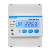
The DTSU666-HW features a display for real-time monitoring of various electrical parameters, including positive and negative active energy, phase voltages (UA, UB, UC), phase currents (IA, IB, IC), total and phase active powers (PFt, PA, PB, PC), and total and phase power factors (PFt, PFa, PFb, PFc). The display also allows for parameter settings such as current transformer ratio (CT), potential transformer ratio (PT), communication protocol, Modbus address, baud rate, wiring mode, rotation display time, backlight illumination time, and channel switchover (transformer or direct connection).
The device supports various communication baud rates (4800, 9600, 19200, 115200 bps, with 9600 bps as default) and different communication protocols (e.g., none parity, even parity, odd parity with 1 or 2 stop bits). These configurable settings ensure compatibility with a wide range of communication environments.
Important Technical Specifications
- Nominal Voltage: 230 V AC/400 V AC, 50 Hz/60 Hz.
- Current Measurement Range:
- Direct connection: 0-80 A.
- Connection through current transformers: > 80 A.
- Voltage Measurement Range: 90–1000 V (line voltage). Potential transformers are required if the voltage is greater than 500 V.
- Electricity Metering Accuracy: Class 1 (error within ±1%).
- Power Grid System: Three-phase four-wire or three-phase three-wire.
- Baud Rate: 4800/9600/19200/115200 bps (default value: 9600 bps).
- Operating Temperature: -25°C to +60°C.
- Installation Mode: Guide rail-mounted (DIN35mm).
- Certification: CE, RCM, and UKCA.
- Dimensions: 101 mm (height) x 72 mm (width) x 80 mm (depth).
- Power Consumption of Voltage: 1.5W, 6VA.
- Terminal Screw Torque:
- Terminals 1, 3, 4, 6, 7, 9, 10, 12: Maximum 1.7 N·m, recommended 0.9–1.1 N·m.
- Terminals 31, 33, 34, 36, 37, 39, 24, 25: Maximum 0.4 N·m, recommended 0.15-0.25 N·m.
- Cable Specifications:
- Channel 1 voltage cable (UA-1, UB-4, UC-7, UN-10): Single-core outdoor copper cable, 25 mm² cross-sectional area, 10 mm outer diameter.
- Channel 2 voltage cable (UA-1, UB-4, UC-7, UN-10): Single-core outdoor copper cable, 4-25 mm² cross-sectional area, 5-10 mm outer diameter.
- Channel 2 current transformer cable (IA*-31, IA-33, IB*-34, IB-36, IC*-37, IC-39): Single-core outdoor copper cable, 2-4 mm² cross-sectional area, 3-5 mm outer diameter.
- Communications cable (RS485A-24, RS485B-25): Two-core outdoor shielded twisted pair copper cable, 0.25-1.5 mm² cross-sectional area, 4-11 mm outer diameter.
Usage Features
The DTSU666-HW is designed for ease of installation and operation. It is guide rail-mounted, allowing for quick and secure installation in standard electrical cabinets. The front panel features a clear display and intuitive buttons (SET, ESC, ←) for navigation and parameter configuration.
Wiring Scenarios: The device supports various wiring configurations based on current and line voltage:
- Current ≤ 80 A, Line Voltage ≤ 500 V: Direct connection for both current and voltage.
- Current > 80 A, Line Voltage ≤ 500 V: Connection through current transformers for current, direct connection for voltage.
- Current ≥ 0 A, Line Voltage > 500 V: Connection through current transformers for current, and potential transformers for voltage.
Networking: It can be integrated into SmartLogger or Smart Dongle networking scenarios. In SmartLogger scenarios, the power meter connects directly to the SmartLogger. In non-SmartLogger scenarios, it connects to the inverter. Shielded twisted pair cables are recommended for communication to ensure signal integrity.
Parameter Settings: The device allows users to configure critical parameters such as CT and PT ratios, Modbus address, and baud rate. This flexibility is essential for adapting the meter to specific installation requirements and ensuring accurate measurements. The default user password for accessing settings is 701.
Display Functionality: The display provides comprehensive real-time data, which can be viewed in a fixed display mode or a rotation display mode with a configurable time interval. This allows for continuous monitoring of key electrical parameters. The backlight illumination time is also configurable, with options for "steady on" or a set duration without key operation.
Maintenance Features
The DTSU666-HW is designed for reliability, but proper installation and occasional checks are important for optimal performance.
Installation Verification:
- Ensure all mounting brackets are securely installed and screws are tightened.
- Verify that all cables are reliably connected with correct polarity and without short circuits. This includes checking the phase sequence of voltage and current, and ensuring the high and low ends of current transformers are correctly connected.
Troubleshooting: The manual provides a troubleshooting guide for common issues:
- No display after power-on: Check cable connections and ensure the correct voltage is supplied to the meter.
- Abnormal RS485 communication: Verify the RS485 communication cable for disconnections, short circuits, or reversed connections. Crucially, ensure that the communication address, baud rate, data bit, and parity bit of the meter match those of the inverter or connected device.
- Inaccurate metering: Confirm correct cable connections and phase sequence. If negative power values (Pa, Pb, Pc) are displayed, it indicates incorrect connection of the current transformer's high and low ends, which needs to be corrected.
Fuse Protection: Each phase of UA, UB, and UC in the Smart Power Sensor is equipped with a fuse and a thermistor to prevent damage from external short circuits. This internal protection eliminates the need for external fuse protection for these phases.
Grounding: It is critical to ensure that the ground cable is installed securely to prevent electric shocks and ensure safe operation.
The DTSU666-HW is a robust and adaptable smart power sensor, offering essential monitoring and management capabilities for various electrical systems, with user-friendly features for installation, configuration, and maintenance.