Do you have a question about the Huawei ETP4860-B1A2 and is the answer not in the manual?
Describes the power system's overview, installation, commissioning, maintenance, and technical specifications.
For sales engineers, technical support engineers, and maintenance engineers.
Defines safety symbols like DANGER, WARNING, CAUTION, and NOTICE.
Read and observe all safety instructions on the equipment and in this document.
Specifies training and qualification requirements for personnel performing installation and maintenance.
Ensures reliable grounding and safe handling of AC and DC power connections.
Details requirements for installation locations to prevent hazards like fire and equipment damage.
Covers safety procedures for hoisting devices, using ladders, and drilling holes.
Provides critical precautions for handling batteries, including risks of explosion and leakage.
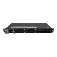
Introduces the ETP4860-B1A2 as a -48 V DC embedded power system with 60 A output.
Highlights features: AC/HVDC input, battery management, communication ports, and hot-swappable modules.
Outlines system configurations for subracks and power distribution units.
Illustrates the front panel layout, identifying components like ground screw and input terminals.
Details the SMU11B's appearance, status indicators, and wiring terminal pin definitions.
Describes the SMU11C's appearance, indicators, DIP switch settings, and wiring terminals.
Explains the rectifier's function and describes its appearance and status indicators.
Details the MUE03A's appearance, power input port, and communication port definitions.
Covers essential information on cable specifications and required installation tools.
Details cable types, maximum current, and cross-sectional area requirements.
Lists required installation tools and instruments, emphasizing the use of insulated handles.
Provides critical dimensions for installing the subrack correctly within a rack.
Step-by-step procedure for installing the subrack, including ground cable and mounting ears.
Covers the installation process for SMU11B, SMU11C, and Rectifier modules.
Provides a detailed procedure for installing the SMU11B module into the subrack.
Guides the installation of the SMU11C module, including DIP switch configuration.
Details the procedure for safely installing a rectifier into its designated slot.
Covers the installation of various signal, communication, power, and battery cables.
Procedure for connecting a dry contact signal cable to the SMU's IO ports.
Connects the battery temperature sensor cable to the SMU's SIG2 port BTE.
Connects the door status sensor cable to the SMU's SIG2 port GAT.
Connects the alarm signal cable to the VD2 port on the monitoring module.
Connects the expansion box COM_IN port to the SMU's COM2 port.
Connects the expansion box COM_IN port to the SMU's COM2 port.
Connects the SMU11C COM1 to Huawei access network equipment for management.
Connects SMU11B FE port for U2000, NetEco, and SNMP network management.
Prepares and installs DC output power cables using appropriate cord end terminals.
Details battery cable preparation, installation, and essential safety precautions.
Covers the installation of AC single-phase, AC dual-live wire, and DC input power cables.
Procedure to connect 220 V AC single-phase input power cables to terminals.
Procedure to connect 110 V AC dual-live wire input power cables to terminals.
Procedure to connect DC input power cables to the designated DC input terminals.
Ensures all screws are secure and rectifiers are properly inserted and locked.
Verifies circuit breakers, terminals, batteries, and power cables are correctly connected.
Confirms cables are securely connected, neatly arranged, and properly labeled.
Details measuring input voltage and switching on the upstream circuit breaker.
Covers logging into the SMU11B WebUI and configuring system parameters.
Steps to set PC IP address and access the SMU WebUI login page.
Guides language selection, date/time setting, and basic battery parameter configuration.
Details installing, logging into, and setting parameters via the LIVE-C mobile application.
Provides steps to obtain and install the LIVE-C APP on a compatible mobile phone.
Outlines prerequisites and procedures for successfully logging into the LIVE-C APP.
Guides display language setup, using the setup wizard, and disabling door status alarms.
Procedure for switching on battery circuit breakers and observing battery status.
Covers backing up settings, restoring defaults, and upgrading software via WebUI.
Explains how to back up the system configuration file to a local computer.
Details the procedure for restoring factory settings, which restarts the monitoring unit.
Provides steps to upgrade software for SMU, BSP, and other devices via WebUI.
Covers software upgrade, password changes, factory reset, and SMU reset using LIVE-C APP.
Steps to access SMU upgrade management and import the software upgrade file.
Details the procedure for changing user passwords for enhanced system security.
Notes that the SMU restarts after factory settings are restored.
Describes the SMU reset process and its impact on connected devices.
Presents a checklist for routine maintenance tasks including electricity, inspection, and grounding.
Provides guides for identifying faults in rectifiers, SMUs, and circuit breakers.
Lists common rectifier faults and their corresponding indicators for diagnosis.
Describes indicators that suggest an SMU is faulty or not communicating.
Identifies faulty circuit breakers based on load fuse status and power supply.
Covers the procedures for safely replacing rectifiers, SMUs, and circuit breakers.
Provides a step-by-step guide for safely removing and installing a rectifier.
Details the procedure for replacing the SMU11B module, including ESD precautions.
Details the procedure for replacing the SMU11C module, including ESD precautions.
Outlines the steps to safely replace a faulty circuit breaker.
Specifies operating, transportation, and storage temperatures, humidity, altitude, and other environmental requirements.
Details AC input system, rated voltage, voltage range, and input frequency specifications.
Details DC input system and rated voltage specifications.
| Brand | Huawei |
|---|---|
| Model | ETP4860-B1A2 |
| Category | Network Hardware |
| Language | English |