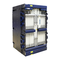
T64/T32
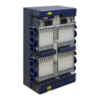
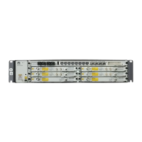
T16
T16
T16
T16
Cabinet Alarm Indicator Cable Connections
(Cascading Mode)
2 Cabinet Alarm Indicator Cable Connections
The LAMP interfaces on the EFI2 board provide 5 V power for the indicators on a
cabinet. It cannot connect to an RJ45 cable intended for the NM_ETH, ETH,
ALMO, or CLK interface; otherwise, the EFI2 board, the connected test instrument,
or the equipment housing the EFI2 board will be damaged.
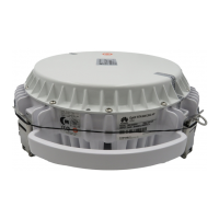
Cabinet indicator
alarm cable
CAUTION
To the drive interface on
the cabinet top indicator
To the drive interface on
the cabinet top indicator
3 Connecting Cabinet Alarm Indicator Cable
You may connect the cabinet alarm indicator cables in all interface areas of the equipment at the same time. For details, see
the Connecting Clock Cables and Cables in the Interface Area procedure in Installing and Routing Clock Cables in this
document.
NOTE
NOTE
The cables are connected in a similar way in multi-subrack configurations although the number and type of
connected subracks may differ. The only difference is the board where the LAMP1/LAMP2 interface is located.
Cabinet Alarm Indicator Cable Connections
(T32 and T16 Subracks Cascaded)
 Loading...