30
Installing Signal Monitoring Cables
e
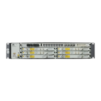
CCUB board
COM_IN port
•Mapping Relationships Between the Signals over Different Cables
For cabinet sharing, the signal monitoring cable is not required for the RTN 900.
RJ-45 Connector of the Network Port to the
Cable on the CCUB (COMIN) Board
RJ-45 Connector (TOD2) of the Network Port to the
Cable on the CSH/CST Board
Pin 1 TX+ White/Orange Pin 6 RX+ White/Orange
Pin 2 TX- Orange Pin 3 RX- Orange
Pin 4 RX+ Blue Pin 8 TX+ Blue
Pin 5 RX- White/Blue Pin 7 TX- White/Blue
Pin 8 GND Brown Pin 5 GND Brown
Pin 3/6/7
No
connected
- Pin 1/2/4
No
connected
-
NOTE
When using the CSHU or CSHUA board, connect the signal monitoring cable to the MON/TOD2 port. The
pin assignment is the same as that of the CSH or CST board.
Before installing a signal monitoring cable, remove the cable already connected to the COM_IN port on the
CCUB board. Then, connect a cable of a proper length to the RTN 900.
NOTE