5
•
Ensure that the PV module output is well insulated to ground.
•
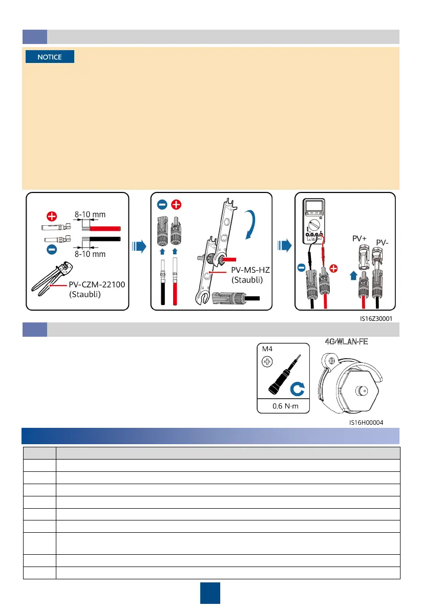
Use the delivered Staubli MC4 metal terminals and DC connectors. Device damage caused by
using other types of metal terminals and DC connectors is not covered by the product
warranty.
•
If the open-end wrench slips, the locking nut is tightened.
•
If PV strings are configured with optimizers, check the cable polarity by referring to the
Smart PV Optimizer Quick Guide
.
•
If the DC input power cables are reversely connected, do not perform operations
immediately. Wait until the night when solar irradiance declines and the PV string current
drops to below 0.5 A. Then set the DC switch to OFF, remove the positive and negative
connectors, and rectify the cable connection. Device damage caused by improper operations
is not covered by the product warranty.
Cables are
connected in the
correct polarity,
Voltage ≤ 1100 V
Click
1 The inverter is installed correctly and securely.
2 Cables are routed properly as required by the customer.
3 The Smart Dongle is installed correctly and securely.
4 Cable ties are evenly distributed and no burr exists.
5 Ground cables are connected correctly and securely.
6 The DC SWITCH and all switches connected to the inverter are set to OFF.
7
The AC output power cable, DC input power cables, and signal cables are connected
correctly and securely.
8 Unused terminals and ports are sealed by watertight caps.
9 The installation space is proper, and the installation environment is clean and tidy.
4
Verifying the Installation
Connecting DC Input Power Cables
3.4
(Optional) Installing the Smart Dongle and Anti-theft Components
3.5
1. Install the Smart Dongle. For details, see the
Smart Dongle Quick Guide
.
2. Install the anti-theft components.
Click
 Loading...