The SUN2000 is installed correctly and securely.
Cables are routed properly as required by the customer.
The communications expansion module is installed correctly and securely.
Cable ties are secured evenly and no burr exists.
The PE cable is connected correctly, securely, and reliably.
The DC switch and all the switches connected to the SUN2000 are set to OFF.
The AC output power cable, DC input power cables, and signal cables are connected correctly
and securely.
Unused terminals and ports are locked by watertight caps.
The installation space is proper, and the installation environment is clean and tidy.
Before turning on the AC switch between the SUN2000 and the power grid, check that the AC
voltage is within the specified range using a multimeter.
1. Turn on the AC switch between the SUN2000 and the power grid.
2. Turn on the DC switch at the bottom of the SUN2000.
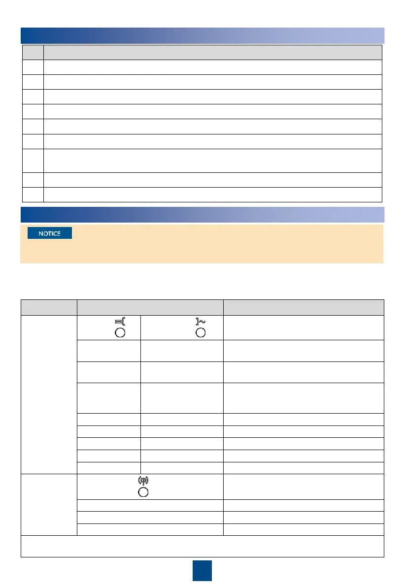
3. Observe the LED indicators to check the operating status of the SUN2000.
The SUN2000 is operating in grid
The DC is on and the AC is off.
Both the DC and AC are on, and the
SUN2000 is not supplying power to the
power grid.
The DC is off and the AC is on.
Both the DC and AC are off.
Communication is in progress.
Note: If LED1, LED2, and LED3 are steady red, the SUN2000 is faulty and needs to be replaced.
Blinking Slowly: On for 1s and Off for 1s; Blinking Fast: On for 0.2s and Off for 0.2s
7
Verifying the Installation
8
Powering On the System
 Loading...