4
1 GND
Ripple control
GND port for the DIN1 to DIN5 signals
2 DIN1
Dry contact for grid scheduling
3 DIN2
4 DIN3
5 DIN4
6 DIN5 Rapid shutdown signal+
For the rapid shutdown DI signal or connecting
to the signal cable of an NS protective device
7 GND GND -
8 - - -
9 485A1 RS485A1 differential signal+
For inverter cascading or connecting to the
RS485 signal port of a SmartLogger
10 485B1 RS485B1 differential signal–
11 485A2 RS485A2 differential signal+
Connecting to the RS485 signal port of a power
meter
12 485B2 RS485B2 differential signal–
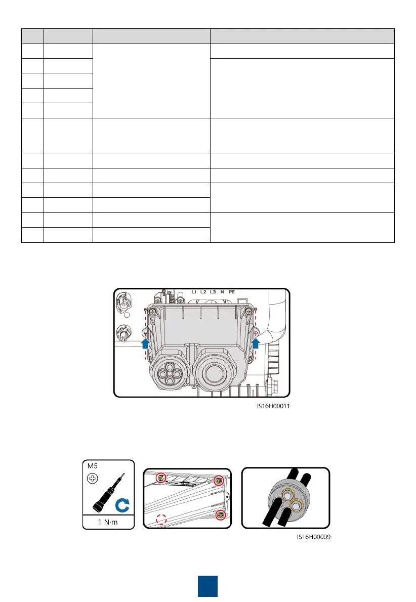
3. Align the pin holes at both ends of the junction box with the positioning pins on the inverter
enclosure to ensure that the screw holes on the junction box are aligned.
4. Install the junction box, seal the unused cable holes in the rubber plugs with waterproof
plugs, and tighten the locking caps.
 Loading...