Do you have a question about the Huawei SUN2000-M1 and is the answer not in the manual?
Specifies installation angle, space, and dimensions for the inverter.
Step-by-step guide for mounting the inverter and securing it.
General precautions and cable requirements before electrical connections.
Instructions for connecting the protective earth (PE) cable to the inverter.
Guide on connecting the AC output power cable, including stripping requirements.
Details on connecting DC input power cables, including connector assembly and polarity.
Procedures for connecting battery cables to the inverter.
Procedures for installing WLAN-FE and 4G Smart Dongles for communication.
General guidance on connecting signal cables and communication port definitions.
Steps to connect RS485 communication cables for cascading multiple inverters.
Instructions for connecting RS485 cables when only a Smart Power Sensor is connected.
Guide for connecting RS485 cables for Smart Power Sensor and energy storage devices.
Procedure for connecting the grid scheduling dry contact signal cable.
Steps for connecting signal cables to a Smart Backup Box.
Checklist of criteria to verify before powering on the inverter.
Steps to power on the system, starting with the battery switch.
Sequence for turning on AC and DC switches for system startup.
Guide to interpreting LED indicators for operating status and communication.
Explains the LED indicators for the WLAN-FE and 4G Smart Dongles.
Steps for downloading the app, registering an installer account, and logging in.
Guide to creating a plant and adding PV plant information in the app.
Instructions for setting up the physical layout of the PV plant in the system.
Steps for accessing and performing device commissioning via the app.
Detailed steps to reset the inverter's login password.
The provided document is a Quick Guide for the SUN2000-(3KTL-10KTL)-M1 solar inverter, detailing its installation, electrical connections, commissioning, and basic operation.
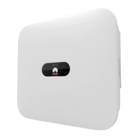
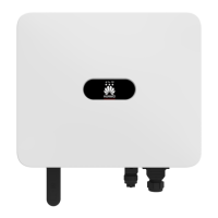
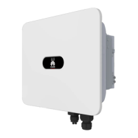
The SUN2000-(3KTL-10KTL)-M1 is a grid-tied PV power system inverter designed for converting DC power from PV modules into AC power for the grid. It features a robust design with a front panel, heat sink, and ventilation valve for efficient operation. Key components include multiple DC input terminals (PV1+/PV1-, PV2+/PV2-), battery terminals (BAT+/BAT-), and an AC output port. For communication and smart functionalities, it includes a communication port (COM) and a Smart Dongle port (GPRS/4G/WLAN-FE). A DC switch is integrated for safety and control. The inverter also has an LED indicator for displaying its operating status and a ground screw for earthing. A hanging kit and mounting bracket are provided for installation.
The installation process begins with mounting the bracket, ensuring proper spacing and angle for optimal performance and heat dissipation. The inverter can be installed on solid concrete walls using M6x60 expansion bolts, with provisions for other wall types if they meet load-bearing requirements. An optional screw for locking the DC switch is available, particularly for Australian standards, to prevent accidental activation. An anti-theft lock can also be installed.
Electrical connections are crucial and must adhere to local installation laws and regulations. Before connecting any cables, the DC switch on the inverter and all other connected switches must be in the OFF position to prevent electric shocks. The PE cable, a single-core outdoor copper cable, should be connected first, with the PE point at the AC output port serving as an equipotential point. Silica gel or paint is recommended around the ground terminal after connection for protection.
The AC output power cable, an outdoor copper cable, requires specific stripping for secure connection to the AC connector. The guide provides detailed instructions for connecting five-core (L1, L2, L3, N, and PE) and similarly, three-core or four-core AC output power cables. It emphasizes ensuring the protection layer is inside the connector, core wires are fully inserted, and the cable is securely connected to prevent malfunction.
For DC input power cables, Staubli MC4 positive and negative metal terminals and DC connectors supplied with the inverter must be used. Incompatible connectors can lead to device damage and void the warranty. Cable polarities must be correctly labeled before installation. If DC input cables are reversely connected, the DC switch and connectors should not be operated immediately; instead, wait until solar irradiance declines and current drops below 0.5 A before correcting the polarities. For PV strings with Smart PV Optimizers, the Smart PV Optimizer Quick Guide should be consulted for cable polarity.
Optional battery cables (BAT+/BAT-) also require correct polarity to prevent inverter damage. The assembly of positive and negative connectors for battery cables follows the same instructions as for DC input power cables. Watertight caps should be properly kept on unused terminals.
The inverter supports Smart Dongles for communication. A WLAN-FE Smart Dongle (SDongleA-05) is provided for FE communication, while a 4G Smart Dongle (SDongleA-03) can be purchased separately for 4G communication. The guide provides quick guides for both types of dongles. For WLAN-FE communication, a CAT 5E outdoor shielded network cable and shielded RJ45 connectors are recommended. For 4G Smart Dongles, a standard SIM card (25 mm x 15 mm, ≥ 64 KB capacity) must be installed in the arrow direction, ensuring the buckle springs back into place when reinstalling the cover.
Signal cables, if applicable, should be laid out separately from power cables and away from strong interference sources to avoid communication issues. The protection layer of the signal cable must be inside the connector, surplus core wires cut off, and exposed core wires fully inserted and securely connected. If a Smart Dongle is configured, it is advised to install it before connecting the signal cable. The communications port (COM) pin definition is provided for various signal cables, including RS485 communications cables for inverter cascading, Smart Power Sensor connection, and energy storage device connection. Grid scheduling dry contact signal cables and signal cables for a Smart Backup Box also connect to the COM port, with specific pin assignments.
Two main networking scenarios are described: Smart Dongle Networking and SmartLogger Networking. In the Smart Dongle scenario, a SmartLogger cannot be connected. A Smart Power Sensor is necessary for export limitation. Up to 10 devices can connect to WLAN-FE and 4G Smart Dongles, excluding Smart Power Sensors connected to RS485A2 and RS485B2 ports. If a battery is connected, a maximum of three inverters can be cascaded, with one inverter connected to the battery and the Smart Dongle. If SUN2000-(3KTL-10KTL)-M1 and SUN2000-(2KTL-6KTL)-L1 are cascaded, a maximum of three inverters can be cascaded.
In the SmartLogger Networking scenario, the Smart Dongle cannot be connected. A single SmartLogger can connect to a maximum of 80 devices, including inverters, Smart Power Sensors, and EMI, though connecting fewer than 30 devices per RS485 route is advised. The Smart Power Sensor is also necessary for export limitation and can be connected to a separate COM port to ensure system response speed.
Before powering on, a thorough installation verification is required. This includes checking that the inverter is securely installed, cables are routed properly, the Smart Dongle is installed correctly, cable ties are evenly distributed, the PE cable is securely connected, the DC switch and all other switches are in the OFF position, all power and signal cables are connected securely, unused terminals and ports are sealed with watertight caps, and the installation space is clean and tidy.
To power on the system, first, ensure the AC voltage is within the specified range using a multimeter. If a battery is connected, turn on the battery switch. Then, turn on the AC switch between the solar inverter and the power grid. If an LG battery is connected, the DC switch must be turned on within 1 minute after the AC switch; otherwise, the inverter will shut down and restart. Optionally, remove the screw for locking the DC switch. Finally, turn on the DC switch between the PV string and the solar inverter (if any), and then the DC switch at the bottom of the solar inverter.
The inverter's operating status can be observed via its LEDs. Different blinking patterns and colors indicate various states, such as operating in grid-tied mode, DC or AC on/off, communication in progress, or fault conditions. For Smart Dongles, LED indicators show status like secure power-on, router connection parameters, connection to the management system, and communication with the inverter.
Commissioning involves downloading the FusionSolar app, which can be done via Huawei AppGallery, solar.huawei.com, or by scanning a QR code. Users can register an installer account, which generates a company-named domain. The app allows for creating PV plants and plant owners. For Smart PV Optimizers, the physical layout can be set using the FusionSolar app or WebUI. This involves uploading a photo of the physical layout template or manually adding PV modules and binding optimizers. The guide emphasizes ensuring optimizers are connected to the inverter before this step, that PV strings have the same number and model of modules/optimizers, and that SN labels are correctly attached to the template.
For SmartLogger networking, the PV Plants Connecting to Huawei Hosting Cloud Quick Guide should be consulted. Device commissioning can be accessed through the FusionSolar app, whether the phone is connected to the internet or not. If connected, the "Device commissioning" option might not be immediately displayed. Logging in as an installer allows access to the device commissioning screen, where settings like power adjustment and battery control parameters (Charge from grid, Control mode, Maximum self-consumption) can be configured.
The guide stresses the importance of changing the initial password for security and keeping it safe. It also advises turning off the AC switch and setting the DC switch to OFF before maintaining optimizers and PV strings to prevent electric shocks. An installation video is available via QR code. Customer service contact information, including region, country, service support email, and phone number, is provided for various locations globally. The document concludes with contact details for Huawei Technologies Co., Ltd.
| Model | SUN2000-M1 |
|---|---|
| Manufacturer | Huawei |
| Max Efficiency | 98.6% |
| Max DC Voltage | 1100 V |
| Number of MPPTs | 2 |
| Rated AC Grid Frequency | 50 Hz / 60 Hz |
| Adjustable Power Factor Range | 0.8 leading to 0.8 lagging |
| Total Harmonic Distortion (THD) | <3% |
| DC Connection | MC4 |
| Cooling | Natural Convection |
| Protection Degree | IP65 |
| Weight | 17 kg |
| MPPT Efficiency | 99.9% |
| Cooling Method | Natural Convection |
| Protection Level | IP65 |
| Max Input Current | 11A |
| Max AC Power | 5.5 kW |
| Rated AC Voltage | 230V |
| AC Voltage Range | 180 V - 276 V |
| Operating Temperature Range | -25°C to 60°C |
| Dimensions | 525 x 470 x 146 mm |
| Maximum Output Power | 5.5 kW |