Do you have a question about the Hubbell EVP Series and is the answer not in the manual?
Connect arrester ground to apparatus and station grounds, utilizing a reliable common ground network.
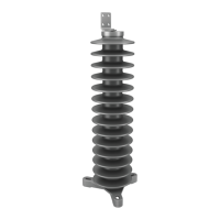
Contains zinc oxide valve elements overwrapped with epoxy-impregnated fiberglass in a polymer weathershed housing.
Ensure continuous phase-to-ground voltage does not exceed arrester's rated voltage (Ur/Uc).
Inspect for damage upon receipt; do not install if damaged. Register claims with the common carrier.
Install electrically close to equipment to be protected, keeping connections short and direct.
Usable from 0-12,000 ft altitude; max temp 60°C, weighted avg 45°C, min -60°C.
Ensure feet are firm before tightening foundation bolts to avoid unnecessary stresses in end fittings.
For base-mounted units, shim as necessary under all but one foot for perpendicularity.
Erect multi-unit arresters in the exact order identified on the outline drawing and nameplate.
Install grading ring on the line end if required, using provided hardware as per outline drawing.
Requires an insulating base; install discharge counter and bases as shown on outline drawings.
Disconnect from line before inspection; install temporary ground on line end to discharge static charge.
Store arresters covered, dry, and clean. Most packaging is recyclable; adhere to regulations.
This manual describes the installation and maintenance of Hubbell Power Systems' EVP-series polymer-housed surge arresters. These devices are designed to protect electrical equipment by limiting surge voltage. They achieve this by conducting surge current to ground, thereby preventing damage to the protected apparatus.
The EVP-series surge arresters are single-pole devices suitable for outdoor use. They are constructed in accordance with the latest revisions of industry standards IEEE C62.11 and IEC 60099-4. Each arrester unit comprises multiple vertically stacked zinc oxide valve elements. These elements are overwrapped with an epoxy-impregnated fiberglass filament wrap and enclosed within ESP® polymer weathershed housing(s). The specific design ordered dictates the type of metal end fittings attached to the housing(s). For three-phase installations, three arresters are required. Most arresters are shipped as a single assembled unit, except for special multi-rated designs, which consist of separate units that must be stacked and bolted together in the field during installation.
The equipment should only be installed and serviced by competent personnel familiar with good safety practices. Before installation, it is crucial to verify that the product's nameplate information matches the application requirements and the outline drawing.
Upon receipt, arresters should be carefully removed from their carton or crate and inspected for any damage resulting from rough handling. If damage is apparent, the arrester should not be installed, and claims for shipping damage should be registered immediately with the common carrier. The arrester's model number, rated voltage (Ur for IEC arresters), and MCOV (Uc for IEC arresters) are identified on the nameplate. This information must be checked against the shipping memorandum.
Arresters must be applied where the continuous phase-to-ground voltage at the arrester location does not exceed the arrester's continuous voltage capability as indicated on the nameplate. The physical size of the arrester may not necessarily determine its voltage rating. It is critical not to install an arrester if its type, rated voltage (Ur), and maximum continuous operating voltage (Uc) on the nameplate and packaging labels do not exactly match. The arrester should be installed electrically as close as practicable to the equipment it is intended to protect, with short and direct connections. Footings for outdoor piers or supports should extend below the frost line and be elevated sufficiently above the ground line to meet personnel safety requirements.
EVP-series arresters can be used at altitudes ranging from 0 to 12,000 feet (3600m). They are suitable for locations where the maximum temperature does not exceed 60°C, and the weighted average temperature does not exceed 45°C. The minimum operating temperature is -60°C.
When mounting, ensure that all feet are firmly positioned before tightening foundation bolts to avoid unnecessary stresses in the end fittings. Tighten the bolts firmly. Some lower voltage arresters may be mounted horizontally; however, it is advisable to consult a Hubbell Power Systems sales representative to confirm horizontal mounting is permissible for a specific arrester.
Line and ground hardware are shipped unassembled with the arrester and are typically found inside the carton or crate. Install the supplied line and ground terminals to the arrester as indicated on the outline drawing. The arrester ground must be connected to the apparatus ground and the main station ground using a reliable common ground network with low resistance. Line connections should not impose excessive mechanical stress on the arrester.
For base-mounted arresters, shims should be used as necessary under all but one foot to ensure perpendicularity to the foundation.
Special multi-rated arresters consist of two or more units. One or more of these units can be shorted by a supplied shorting bar to achieve an arrester voltage rating lower than the rating of the arrester without the shorting bar. The shorting bar connects to the arrester using provided terminals. The outline drawing indicates the locations for terminal installation. Multi-unit arresters must be erected in the exact order specified on the outline drawing and the nameplate attached to the lower end fitting of the bottom unit. Carefully check that each unit is vertical, shimming under all but one foot if necessary, and repeat this procedure for additional units.
Depending on the arrester's voltage rating and length, a grading ring may be required on the line end. The outline drawing specifies the correct location for installing the grading ring. Install the ring with the provided hardware. Grading rings are shipped on a separate pallet when required.
An insulating base is required when installing a discharge counter with arresters. Both discharge counters and insulating bases are available as accessories through HPS sales personnel. Install these components as shown on the outline drawings. Always ensure that the ground connection is firmly made before connecting the arrester to an energized line. If an insulating unit is used at the ground end to permit the use of a discharge counter, the discharge counter must be connected (or the insulating unit shorted out) before connecting the arrester to an energized line.
EVP arresters can be stored outdoors if suitable precautions are taken to prevent deterioration of the packing material. Arresters should be covered with a waterproof covering to keep them dry, clean, and free from litter until used. In climates where outdoor temperature and humidity extremes rapidly deteriorate the packing material, it is recommended that arresters intended for outdoor storage be removed from their packing and bolted (vertically) to a skid.
Most EVP packaging is recyclable in accordance with federal, state, and local regulations. Users are encouraged to adhere to all applicable regulations.
Before inspecting or handling an arrester, it must be disconnected from the line. When a metal-oxide arrester is disconnected from an energized line, it may retain a small amount of static charge. As a precautionary measure, install a temporary ground on the line end of the arrester after it has been disconnected from the line. This ensures that any retained charge is discharged to ground. The temporary ground must be removed before the arrester is re-installed.
These arresters do not require testing. No test that applies power voltage in excess of the maximum arrester voltage rating should be conducted without consulting Hubbell. There is no single field test that can indicate the complete operating characteristics of the arrester.
| Category | Industrial Electrical |
|---|---|
| Series | EVP Series |
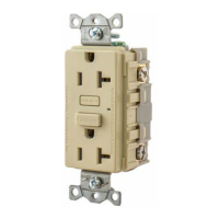
| Current Rating | 30A |
| IP Rating | IP67 |
| Mounting Type | Panel Mount |
| Termination Type | Screw Terminal |