1. What is a GFCI?
A GFCI receptacle is different from conven-
tional receptacles. In the event of a ground
fault, a GFCI will trip and quickly stop the
flow of electricity to prevent serious injury.
Definition of a ground fault:
Instead of following its normal safe path,
electricity passes through a person’s body to
reach the ground. For example, a defective
appliance can cause a ground fault.
A GFCI receptacle does
not protect against
circuit overloads, short circuits, or shocks.
For example, you can still be shocked if you
touch bare wires while standing on a non-
conducting surface, such as a wood floor.
3. Should you install it?
Installing a GFCI receptacle can be more
complicated than installing a conventional
receptacle.
Make sure that you:
• Understand basic wiring principles and
techniques
• Can interpret wiring diagrams
• Have circuit wiring experience
• Are prepared to take a few minutes to test
your work, making sure that you have wired
the GFCI receptacle correctly
5. Turn the power OFF
Plug an electrical device, such as a lamp or
radio, into the receptacle on which you are
working. Turn the lamp or radio on. Then,
go to the service panel. Find the breaker or
fuse that protects that receptacle. Place the
breaker in the OFF position or completely
remove the fuse. The lamp or radio should
turn OFF.
Next, plug in and turn ON the lamp or radio
at the receptacle’s other outlet to make sure
the power is OFF at both outlets. If the
power is not OFF, stop work and call an
electrician to complete the installation.
6. Identify cables/wires
Important:
Do not install the GFCI receptacle in an
electrical box containing (a) more than 4
wires (not including the grounding wires) or
(b) cables with more than two wires (not
including the grounding wire). Contact a
qualified electrician if either (a) or (b) is
true.
If you are replacing an old receptacle, pull it
out of the electrical box without disconnect-
ing the wires.
• If you see one cable (2-3 wires), it is the
LINE cable. The receptacle is probably in
position C (see diagram to the right).
Remove the receptacle and go to step 7A.
• If you see two cables (4-6 wires), the
receptacle is probably in position A or B
(see diagram to the right). Follow steps
a-e of the procedure to the right.
Procedure: box with two cables (4-6 wires)
(a) Detach one cable’s white and hot wires
from the receptacle and cap each one
separately with a wire connector. Make
sure that they are from the same cable.
(b) Re-install the receptacle in the electrical
box, attach the faceplate, then turn the
power ON at the service panel.
(c) Determine if power is flowing to the
receptacle. If so, the capped wires are
the LOAD wires. If not the capped wires
are the LINE wires.
(d) Turn the power OFF at the service panel,
label the LINE and LOAD wires, then
remove the receptacle.
(e) Go to step 7B.
Placement in circuit:
The GFCI’s place in the circuit determines if
it protects other receptacles in the circuit.
Sample circuit
Placing the GFCI in position A will also
provide protection to “load side”
receptacles B and C. On the other hand,
placing the GFCI in position C will not
provide protection to receptacles A or B.
Remember that receptacles A, B, and C
can be in different rooms.
• To prevent severe shock or
electrocution, always turn the power
OFF at the service panel before
working with wiring.
• Use this GFCI receptacle with copper
or copper-clad wire. Do not use it
with aluminum wire.
• Do not install this GFCI receptacle on
a circuit that powers life support
equipment because if the GFCI trips
it will shut down the equipment.
• For installation in wet locations,
protect the GFCI receptacle with a
weatherproof cover that will keep
both the receptacle and any plugs
dry.
• Must be installed in accordance with
national and local electrical codes.
CAUTION
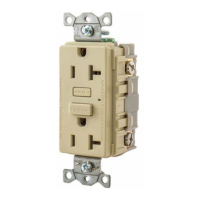
2. The GFCI’s features
Grounding terminal
(Green): Connection
for bare copper or
green wire.
LINE
White terminal (Silver):
Connection for the LINE
cable’s white wire.
LOAD
White terminal (Silver):
Connection for the LOAD
cable’s white wire.
Screw (terminal) colors:
Green = grounding terminal
Silver = white terminals
Brass = hot terminals
LINE
Hot terminal (Brass):
Connection for the LINE
cable’s black wire.
LOAD
Hot terminal (Brass):
Connection for the LOAD
cable’s black wire.
A yellow sticker covers the
LOAD terminals. Do not
remove the sticker at this
time.
FRONT VIEW
Receptacle
Outlet
TEST button:
See step 8
RESET button:
See step 8
Outlet
Mounting
bracket
Cable Wires
Installing and
Testing a GFCI
Receptacle
Please read this leaflet
completely before get-
ting started
4. LINE vs. LOAD
A cable consists of 2 or 3 wires.
LINE cable:
Delivers power from the service panel
(breaker panel or fuse box) to the GFCI. If
there is only one cable entering the electrical
box, it is the LINE cable. This cable should be
connected to the GFCI’s LINE terminals only.
LOAD cable:
Delivers power from the GFCI to another
receptacle in the circuit. This cable should be
connected to the GFCI’s LOAD terminals
only. The LOAD terminals are under the
yellow sticker. Do not remove the sticker at
this time.
PD2490 (Page 1) (English) 09/11
!
LINE
LOADLOAD
LINE LINE
Service
Panel
A B C
BACK VIEW
Light Emitting Diode
(LED)
®
Wiring Systems