8. Test your work
Why perform this test?
• If you miswired the GFCI it may not prevent personal injury or death due to a ground fault
(electrical shock).
Procedure:
(a) Turn the power ON at the service panel. Press the RESET button
fully. The GFCI cannot be reset until it is wired correctly and
power is supplied to the device. Plug a lamp or radio into the
GFCI (and leave it plugged-in) to verify that the power is ON. If there
is no power, go to Troubleshooting.
(b) Press the TEST button in order to trip the device. This should stop the
flow of electricity, making the radio or lamp shut OFF. Note that the
RESET button will pop-out. If the power stays ON, go to Troubleshooting.
If the power goes OFF, you have installed the GFCI receptacle correctly.
To restore power, press the RESET button. If the red Light Emitting
Diode (LED) begins to flash, or if the GFCI cannot be reset, the
receptacle has lost its GFCI protection and should be replaced
immediately.
(c) If you installed your GFCI using step 7B, plug a lamp or radio into
surrounding receptacles to see which one(s), in addition to the
GFCI, lost power when you pressed the TEST button. Do not plug
life saving devices into any receptacles that lost power. Place a
“GFCI Protected” sticker on every receptacle that lost power.
(d) Press the TEST button (then RESET button) every month to assure proper operation.
RESET BUTTON MUST BE FULLY DEPRESSED FOR FULL ENGAGEMENT.
A: One cable (2 or 3 wires) entering the box OR B: Two cables (4 or 6 wires) entering the box
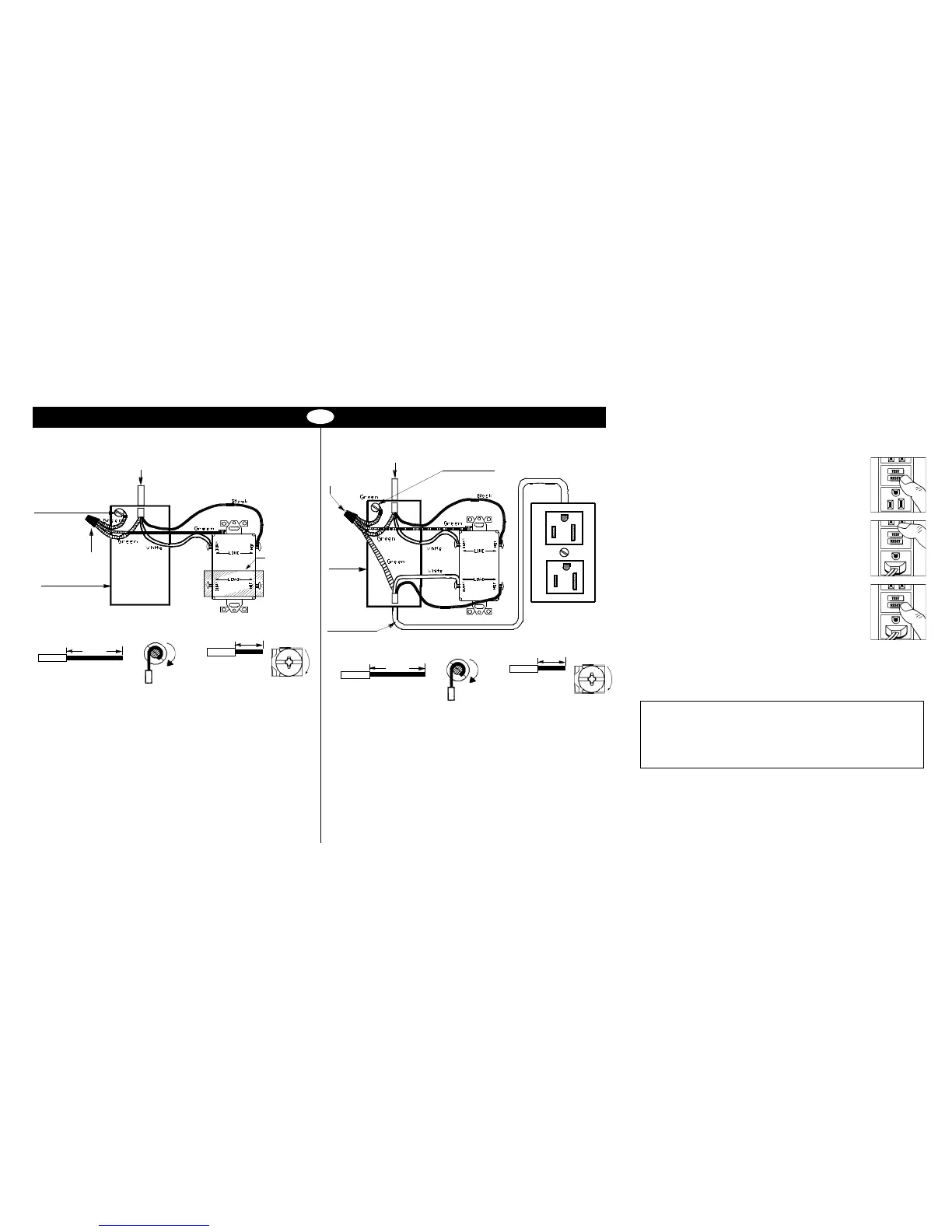
7. Connect the wires (choose A or B) ... only after reading other side completely
Connect the LINE cable wires to the LINE terminals:
• The white wire connects to the White terminal (Silver)
• The black wire connects to the Hot terminal (Brass)
Connect the grounding wire (only if there is a grounding wire):
• For a box with no grounding terminal: (diagram not shown) Connect the LINE
cable’s bare copper (or green) wire directly to the grounding terminal on the
GFCI receptacle.
• For a box with a grounding terminal: (diagram shown above) Connect a 6-inch
bare copper (or green) 12 or 14 AWG wire to the grounding terminal on the GFCI.
Also connect a similar wire to the groundomg terminal on the box. Connect the
ends of these wires to the LINE cable’s bare copper (or green) wire using a wire
connector. If these wires are already in place, check the connections.
Complete the installation:
• Fold the wires into the box, keeping the grounding wire away from the White
and Hot terminals. Screw the receptacle to the box and attach the faceplate.
• Go to step 8
TROUBLESHOOTING
Turn the power OFF and check the wire connections against the appropriate wiring
diagram in step 7A or 7B. Make sure that there are no loose wires or loose connections.
Also, it is possible that you reversed the LINE and LOAD connections. LINE/LOAD
reversal will be indicated by power remaining OFF at the GFCI and by the Reset
Button not staying in. Reverse the LINE and LOAD connections if necessary. Start the
test from the beginning of step 8 if you rewired any connections to the GFCI.
LINE cable brings
power to the GFCI
Grounding connection
to box (if box has a
grounding terminal)
Wire
connector
Electrical box
Yellow sticker
remains in
place to cover
the LOAD
terminals
Connect the LINE cable wires to the LINE terminals:
• The white wire connects to the White terminal (Silver)
• The black wire connects to the Hot terminal (Brass)
Connect the LOAD cable wires to the LOAD terminals:
• Remove the yellow sticker to reveal the LOAD terminals
• The white wire connects to the White terminal (Silver)
• The black wire connects to the Hot terminal (Brass)
Connect the grounding wires as shown above (only if there is a grounding wire):
• Connect a 6-inch bare copper (or green) 12 or 14 AWG wire to the grounding
terminal on the GFCI. If the box has a grounding terminal, also connect a
similar wire to the grounding terminal on the box. Connect the ends of these
wires to the LINE and LOAD cable’s bare copper (or green) wire using a wire
connector. If these wires are already in place, check the connections.
Complete the installation:
• Fold the wires into the box, keeping the grounding wire away from the White
and Hot terminals. Screw the receptacle to the box and attach the faceplate.
• Go to step 8
LINE cable brings
power to the GFCI
Wire
connector
Grounding connection
to box (if box has a
grounding terminal)
Electrical
box
LOAD
cable feeds
power to other
receptacle(s)
PD2490 (Page 2) (English) 09/11
GENERAL INFORMATION
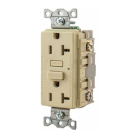
GFCI receptacle rating: 20 Amps, 120 Volts 60 Hz
About wire connections
Clockwise, 2/3 of the
way around the screw
Wire
1 inch
Wire
½ inch
Insert wire behind the
back wire clamp and
tighten down screw
Side Wire
Back Wire
About wire connections
Clockwise, 2/3 of the
way around the screw
Wire
1 inch
Wire
½ inch
Insert wire behind the
back wire clamp and
tighten down screw
Side Wire
Back Wire
Wiring Device-Kellems
Hubbell Incorporated (Delaware)
Shelton, CT 06484
1-800-288-6000
www.hubbell-wiring.com
 Loading...