Form creation date: 01.04.2008
Document creation date: 13.01.2020
5 / 18
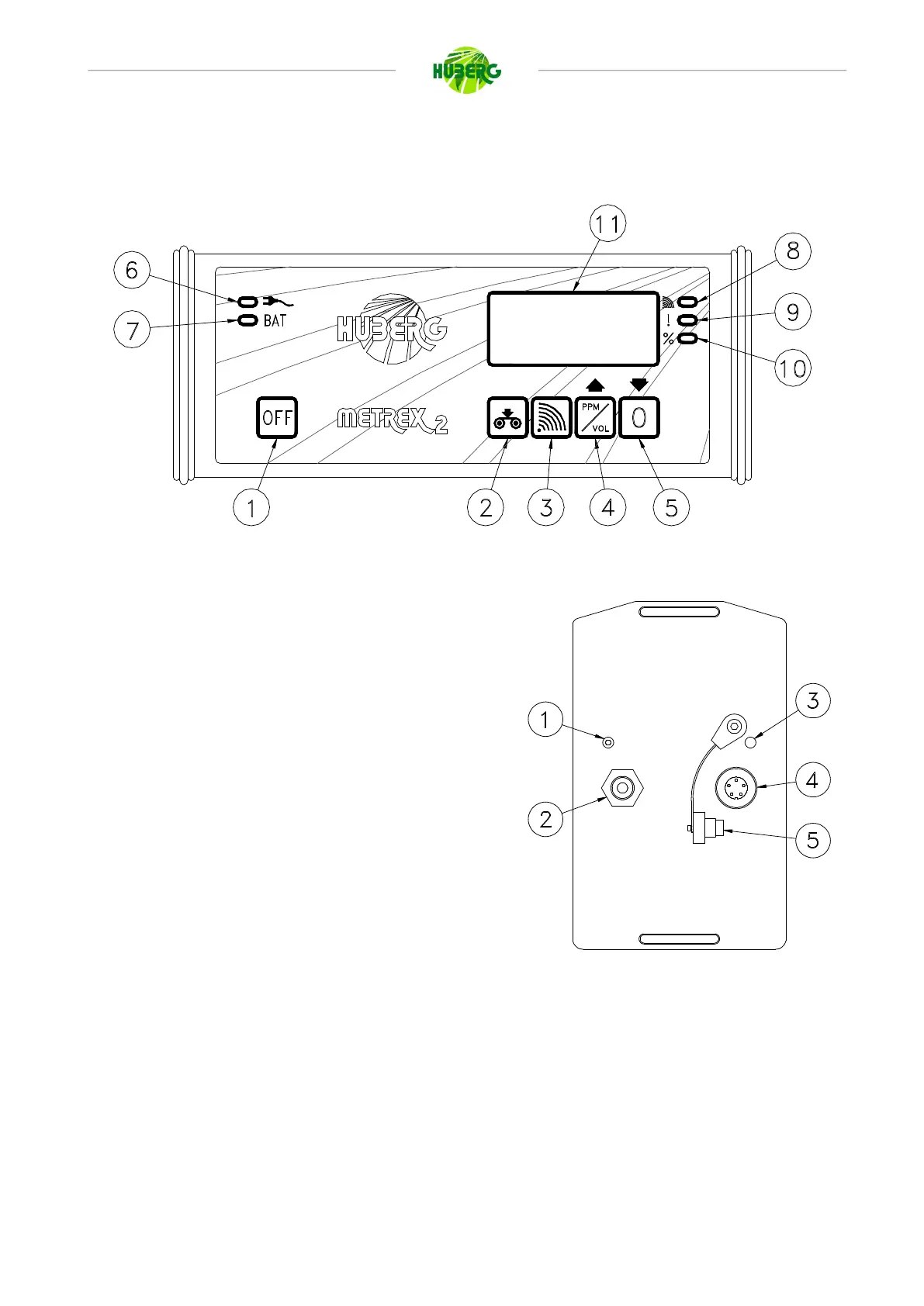
2.0 KEYBOARD AND CONNECTIONS
Figure 1
1. Switch OFF button
2. Data recording button
3. Switch ON/OFF acoustic signal button
4. Switch button PPM/VOL/LEL button
5. Auto zeroing button
6. 220 V~ connection LED
7. Battery recharge LED
8. ON/OFF acoustic signal LED
9. Alarm threshold LED
10. VOL scale LED
11. Display
Figure 2
1. Air outlet
2. Quick coupling for probes
3. Buzzer
4. Socket for battery charger/serial port for data download
5. Cover