56 H U D S O N T E R R A P L A N E
Now loosen instrument panel gear bracket and allow it to shift to match gear
column position and retighten. This will correct any misalignment of gear column.
Worm Shaft and Worm
The main or worm shaft is carried on two taper roller bearings which are
maintained in proper adjustment by a shim pack (B) which is properly selected when
the gear is built. See Figure 47.
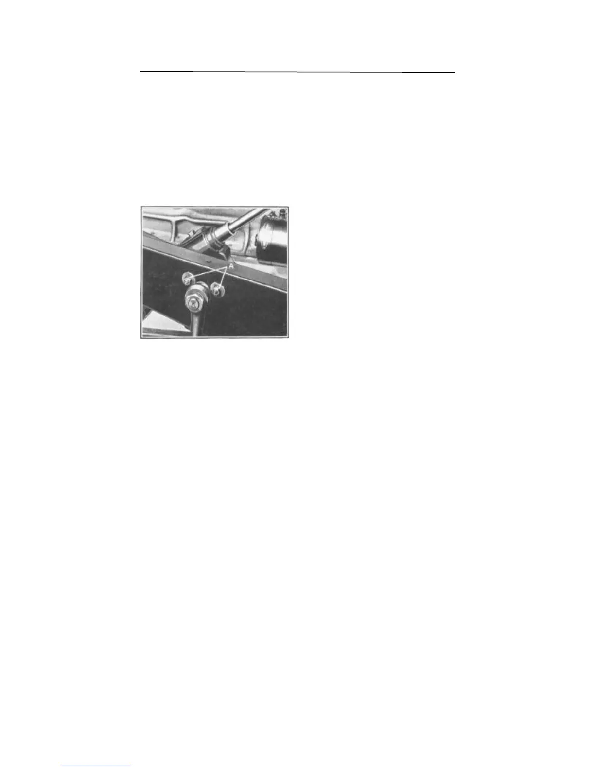
Adjustment—Worm Bearings
Worm bearing adjustment should be
correct before other adjustments are
made. To adjust, loosen four worm cover
screws (A) (two not shown), Figure 47,
Vs". Use a knife to separate the top
shim (B), passing blade all the way around
between shims, care being taken not to
mutilate the remaining shims. Remove
only one shim at a time between inspec-
tions to remove end play. Care should be
taken not to set up stiffness in worm bear-
ings.
Now revolve hand wheel to determine
if any stiffness exists. If so, too many
shims have been removed or gear is
misaligned in car.
Cross Shaft and Roller Tooth
The mesh between the worm and roller tooth is adjusted by a screw (C), Figure
47, extending through right side of the gear housing. A flat washer (D), assembled
to the inner end of screw (C), fits into a slot in the roller tooth shaft to control the
movement of the roller tooth. A lock plate (E) is used to secure the adjustment and
this, in turn, is held in place by a cap (F) which screws onto the adjusting screw (C),
.
Adjustment—Cross Shaft and Roller Tooth
To adjust for closer mesh of the roller tooth and worm, remove cap (F), Figure 47,
slide off lock plate (E) far enough to clear lock boss on roller shaft cover (G). Place
steering wheel in mid-position or straight ahead driving position. The adjusting screw
(C) is then tightened into the housing, then backed off just enough to prevent
binding. Check the amount of play at the end of the ball arm. It is advisable to leave
a slight amount of play at this point rather than to tighten too much.
The lock plate (E) is set in position against the roller shaft cover (G) and locked
in position. Replace adjusting screw cap (F) and tighten in place.
Figure 48
 Loading...