16 FUEL—CARBURETION
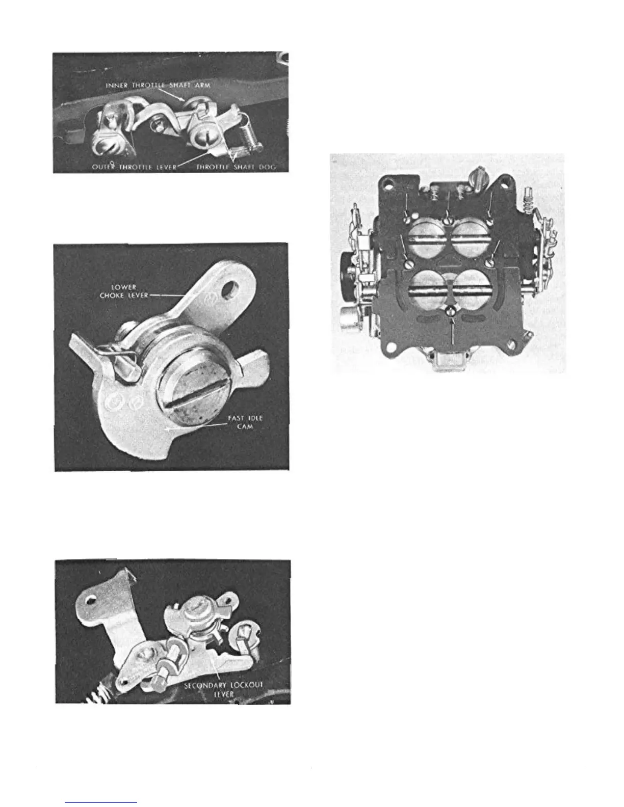
FIGURE 10—Primary Throttle Shaft Arm
and Lever Assembly
Assemble fast idle cam and spring assembly and lower
choke lever placing the assembly on the attaching screw.
FIGURE 11—Fast Idle Cam and Spring
Assembly
Place the secondary lockout lever against boss and
install the fast idle cam assembly in position on the boss.
The levers must operate freely.
FIGURE 12—Secondary Lockout and Fast
Idle Cam Assembled
Install auxiliary throttle shaft and auxiliary throttle
valves.
Using a new gasket, assemble the throttle flange on the
carburetor body. Assemble while holding auxiliary throttle
valves closed.
CAUTION: Tighten the screws indicated in Figure
13 securely to prevent leakage between the body
and throttle flange.
FIGURE 13—Location of Body to Flange
Screws-
Assembling Carburetor Body
Install the primary metering rod jets, (jets with the large
holes) in the accelerator pump side of the carburetor. Then
install the secondary main jets.
Install the two low speed jets in the primary side of the
body.
The steel pump inlet ball check and retainer is installed
in the bottom of the accelerator pump cylinder. A 5A6" six
point socket assists pressing into place.
Install pump passage screw plug and gasket.
The brass pump discharge check needle is installed
point down in the passage below the pump discharge jet
cluster.
Install the accelerator pump discharge cluster gasket
and cluster assembly.
Inspect vacumeter spring. The vacumeter spring affects
both economy and performance. If it appears damaged or
distorted, replace. If there is any doubt, compare it with a
new one. Place the spring in vacumeter bore.
Install lower pump spring in pump cylinder.
Assembling Air Horn
Using a new gasket, install the primary needle and seat;
then install secondary needle and seat assembly.