FUEL—CARBURETION
15
choke, providing a richer mixture.
During the warm-up period, it is necessary to provide a
fast idle speed to prevent engine stalling. This is accom-
plished by a fast idle cam which is rotated by a connector
rod attached to the choke shaft. The fast idle cam prevents
the primary throttle valves from returning to a normal
warm engine idle position while the Climatic ® control is
in operation.
During the starting period if the engine becomes flood-
ed, the choke valve can be partially opened manually. This
can be accomplished by depressing the accelerator pedal
to the floor and engaging the starter. The projection on the
throttle lever (unloader) will rotate the fast idle cam and in
turn partially open the choke valve.
OVERHAUL AND ADJUSTING
Flooding, stumbling on acceleration, and other perfor-
mance complaints in many cases are attributable to dirt,
water, or other contaminants in the carburetor. Therefore,
when removing a carburetor for inspection, do not drain
the fuel bowl. The contents of the carburetor may be
examined for evidence of contamination.
Whenever the carburetor is removed, use care when
handling to prevent damage to the throttle valves. The
lower edge of the throttle valves extend beyond the base of
the carburetor when in the open position.
Figure 8 illustrates the locations and relative lengths of
the air horn attaching screws.
FIGURE 8—Location and Lengths of Air Horn
Attaching Screws
Carefully remove the air horn assembly with the gasket
and attaching parts. If the gasket sticks to the body casting,
the floats may become bent.
The float needles and seats must not be interchanged,
therefore, group the needles and seats with their respective
float assemblies.
The accelerator pump discharge check needle is located
in the passage below the pump jet cluster and may be
removed by inverting the carburetor.
The primary metering rod jets have larger openings than
the secondary jets. Therefore, do not mix. the jets.
When cleaning the carburetor, follow the instructions
for the cleaning solution being used.
Do not use drills or wire to clean jets or ports, this may
result in inadvertent enlarging the openings or ports, af-
fecting carburetor performance.
ASSEMBLY PROCEDURE
Assembling Throttle Flange
Install primary and secondary throttle shafts.
Assemble throttle valves on shafts with trade mark (C)
toward idle ports on primary valves and away from center
of carburetor on secondary valves when viewed from the
bottom. (Use Oval head screws on secondary valves.)
Install idle mixture adjusting screws and springs finger
tight, then loosen one turn.
NOTE: Do not tighten mixture screws tighter than
finger tight.
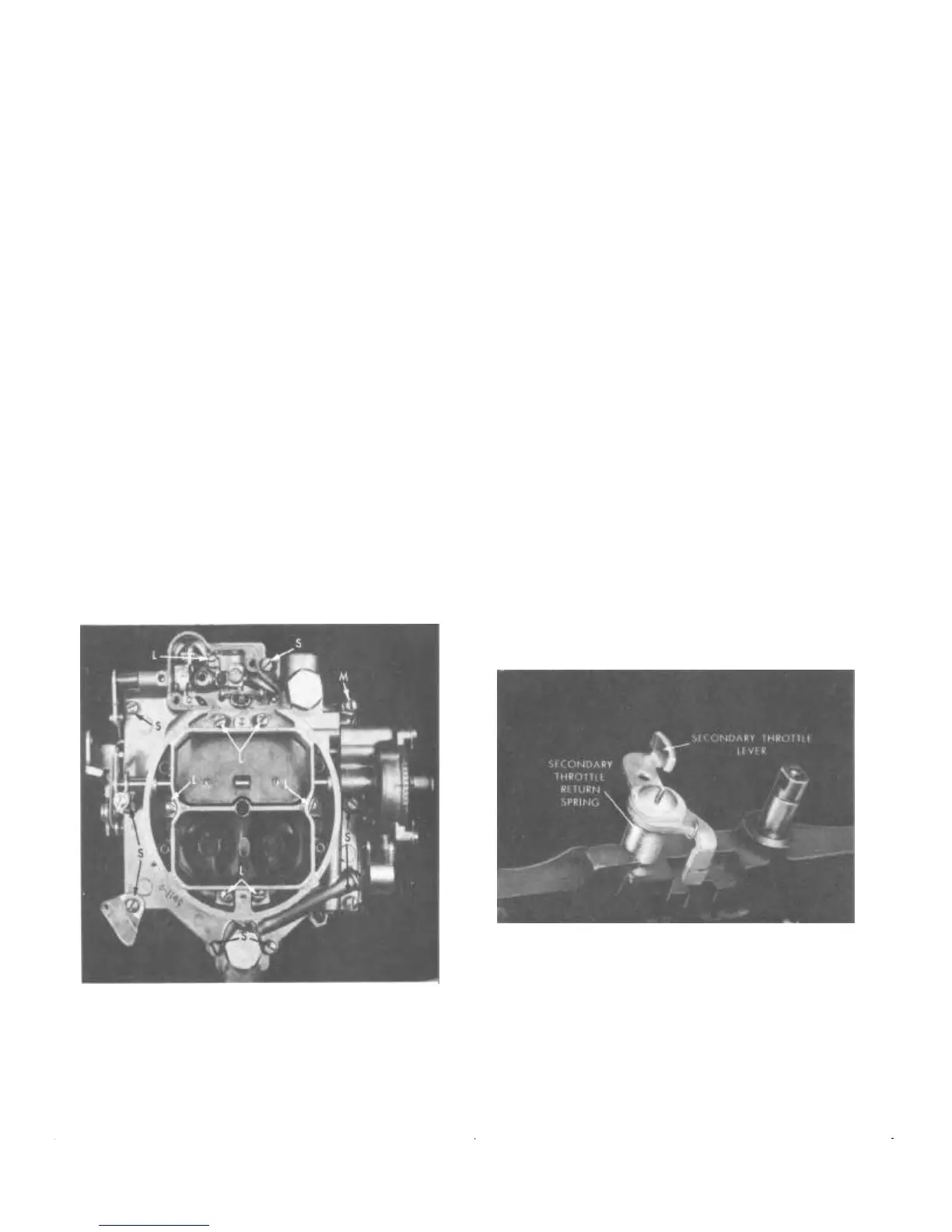
Assemble secondary throttle return spring and throttle
lever on secondary throttle shaft. Install and tighten retain-
ing washer and screw.
Wind the return spring 11/2 turns and hook over secondary
throttle lever.
FIGURE 9—Assembling Secondary Throttle
Lever and Spring
Install primary shaft wave washer, inner throttle shaft
arm, and throttle shaft dog. Hook flex spring on outer
throttle lever and throttle shaft dog and install outer lever
on primary shaft. Install washer and screw.
Install primary to secondary connector rod using a flat
washer on each side of the levers and retain with pin
springs.
 Loading...