24 TRANSMISSION—OVERDRIVE
Due to the similarity between the two units, service
procedures will only be outlined on overdrive equipped
units.
OPERATION OF OVERDRIVE
The overdrive unit, when in operation above the governor
cut-in speed, automatically reduces the engine to rear axle
ratio approximately 30%.
When overdrive operation is desired, the control button
is pushed to the forward position. The car speed is then
increased to a point higher than the cut- in speed, which is
determined by the point setting of the overdrive governor.
As the governor points close, at approximately 26 miles
per hour, the solenoid is energized. This allows the locking
pawl to engage the sun gear hub and balk ring assembly
when the accelerator is momentarily released. When the
accelerator is again depressed the overdrive is in opera-
tion. As this takes place, free wheeling becomes inopera-
tive, since free wheeling is possible only below the cut-in
speed determined by the overdrive governor.
To lock out the overdrive the control button must be
pulled all the way out. This can be done either when the
car is in motion or when it is parked. Locking. out the
overdrive while the car is in motion can he done while the
car is in the free wheeling stage.
The accelerator is depressed slightly so that the engine
is driving the car. The control button can then be pulled out
without depressing the clutch. While still applying pres-
sure to the control button, the accelerator should be mo-
mentarily released to complete the shift.
An alternate method permits pulling the control button
back into conventional position during the time the accel-
erator pedal is fully depressed in the overtake position.
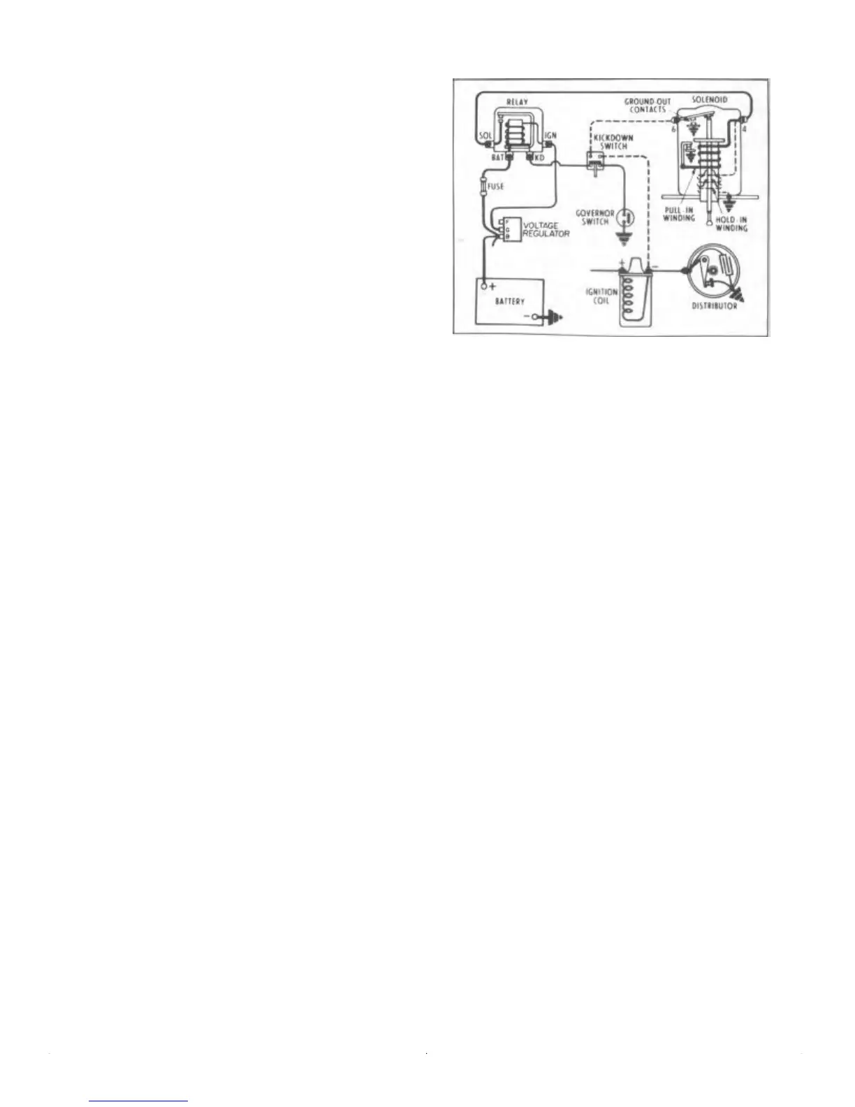
THE ELECTRICAL CIRCUITS
The electrical system consists of the three following cir-
cuits:
Governor Circuit—Light Line
Solenoid Circuit-Heavy Line
Kickdown Circuit—Dotted Line
The governor, solenoid, and kickdown circuits are basi-
cally outlined in Figure 3.
Governor Circuit
The governor circuit starts from the armature terminal of
the voltage regulator. It continues to terminal No. "2"
(Ignition) on the overdrive relay. The current passes
through the relay coil which magnetically controls the
contact points of the solenoid circuit. It continues through
terminal "C" (KD) of the relay through the normally
closed contacts of the kickdown switch on to the governor
terminal and its open contact points.
FIGURE 3—Schematic Drawing Overdrive
Electrical Circuits
Solenoid Circuit
The solenoid circuit starts at the positive terminal of the
battery and continues to the "B" terminal of the voltage
regulator. At this point, it continues to the "Battery" termi-
nal on the overdrive relay, through a 30 ampere fuse, and
to the relay contacts. The circuit is resumed at the
"Solenoid" terminal of the overdrive relay and continues
to the No. "4" terminal of the solenoid and closed contacts
to ground.
Kickdown Circuit
The kickdown circuit starts from the (—) or distributor
side of the ignition coil. It continues to the applied side of
the kickdown switch and resumes at the opposite terminal
on to the No. "6" terminal of the solenoid.
The Circuits in Action
When the car attains a speed of approximately 26 miles per
hour, the centrifugal action of the weights in the governor
closes the contact points, thus completing the circuit from
the ignition switch to the ground.
The relay coil, being energized, closes the relay con-
tacts of the solenoid circuit now being completed and
immediately energizes the actuating and holding coils of
the solenoid moving the pawl into the balk ring and lock
plate.
As soon as the solenoid plunger has been permitted to
enter the lock plate, the pull-in winding contacts in the
solenoid actuating circuit are opened, permitting a de-
creased flow of .current through the holding coil to retain
the plunger in position during the time when the overdrive
is in operation.
The inward movement of the solenoid plunger, in addi-
tion to operating the pull-in winding contacts in the sole-
noid actuating circuit. also closes the ground-out contacts
 Loading...