26 TRANSMISSION—OVERDRIVE
Ground the terminal on the governor. The solenoid should
operate.
Governor Operation Inspection: Suspend the axle and
operate the engine at low speed in high gear. Apply a test
lamp across the governor contact from the live terminal to
the ground strap. The test lamp should light. Now increase
engine speed. The governor cut-in speed will be indicated
when the light goes out.
Summary
By following the above procedure in the proper sequence,
the defective portion of the electrical circuit can be readily
located. If all the preceding items are functioning correct-
ly, the trouble may lie in the solenoid itself, such as burned
points, or the connecting wires may be grounded to the
case.
The kickdown switch should be carefully inspected to
see that none of its four terminals are touching each other.
If the governor circuit is grounded at the kickdown switch,
the grounded circuit will supply current to the relay, oper-
ating the solenoid without the possibility of disengage-
ment. This is usually the case when the car will not free
wheel or shift into reverse.
If the kickdown circuit is internally shunting to the gov-
ernor circuit, the engine will not run upon reaching gover-
nor cut-in speed, as the ignition will obtain a shunt ground
through the governor contact points.
A rubber boot has been provided to exclude water and
dirt from the governor. Moisture or an accumulation of
foreign matter may ground the line terminal on the gover-
nor and cause the solenoid to operate as soon as the
ignition is turned on.
If the mechanical and operating checks do not reveal the
difficulty, internal trouble should be suspected and the
transmission and overdrive removed for examination.
TRANSMISSION REMOVAL
To remove the transmission, disconnect the hydraulic
brake tube bracket that is fastened to the underside of the
body; then disconnect the torque tube at the rear of the
transmission.
Disconnect the hand brake cable at the bellcrank and the
brake cable housing at the bellcrank bracket. Move the rear
axle to the rear to separate the universal joint from the
overdrive main shaft.
Disconnect the speedometer cable, shifter rods, over-
drive control cable, and electrical control wires from the
solenoid and governor.
When removing the transmission from the car, care must
be taken not to damage the transmission clutch shaft.
Always use two guide pins (Tool J-1434) in place of the
two upper attaching cap screws so the transmission clutch
shaft will slide out far enough to clear the clutch pilot
bearing and clutch disc.
TRANSMISSION AND OVERDRIVE DISAS-
SEMBLY
Secure the transmission assembly into a stand and com-
pletely drain its lubricant.
Removing the Torque Tube and
Rear Oil Seal Adapter
Detach the adapter from the overdrive case by removing
the four attaching cap screws. Note that the rear face of
this adapter has a vent groove located on the bottom side.
Separate the adapter and gasket from the overdrive case;
discard the gasket.
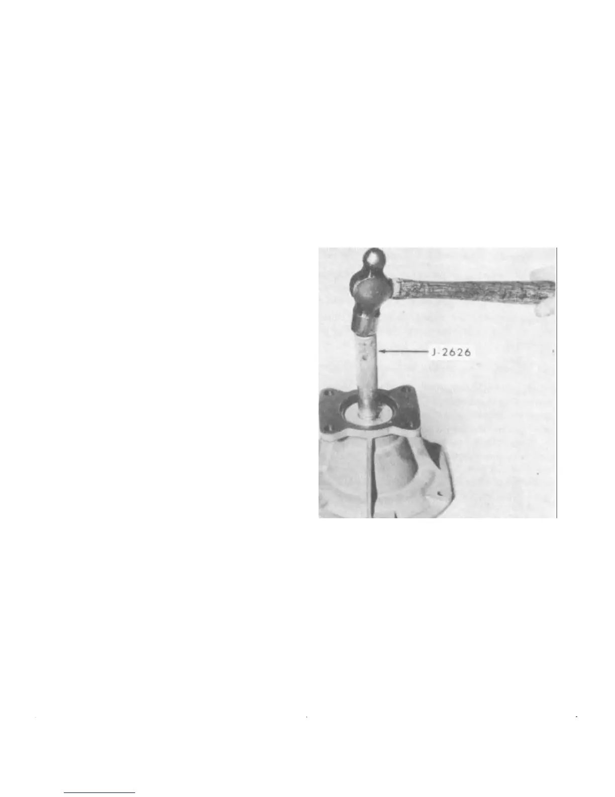
Remove the rear oil seal from the adapter with Tool
J-2626 (Fig. 4).
FIGURE 4—Removing Rear Oil Seal
Disengaging the Shift Shaft
Drive out the tapered lock pin which retains the overdrive
shift shaft assembly in the overdrive case I Fig. 5 .
After the lock pin has been removed, work the shaft
assembly outward to disengage it from the shift rail. Do
not remove the shaft assembly from the overdrive case
unless the oil seal requires replacement. Pulling the shaft
through the seal may damage the sealing lip.
Removing Governor and Solenoid
With a 1-3/8" open end wrench, remove the governor from
the overdrive case.

 Loading...