TRANSMISSION—OVERDRIVE
27
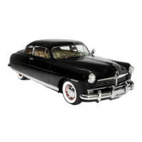
FIGURE 5—Drive Out Tapered Lock Pin
Detach the two solenoid attaching screws and turn the
solenoid one-quarter turn clockwise to release the solenoid
plunger from the overdrive locking pawl.
Removing the Overdrive Case
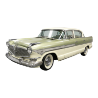
Remove the rear bearing snap ring and spacer washer from
the overdrive main shaft (Fig. 6).
NOTE: On the standard transmission, the rear
bearing is a press fit between the overdrive case
and torque tube and oil seal adapter.
1. Spacer Washer 2. Snap Ring
FIGURE 6—Removing Rear Bearing Snap Ring
and Spacer Washer
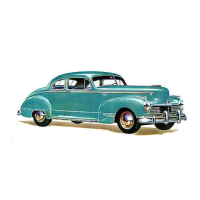
Remove the four cap screws that hold the overdrive case
to the transmission case. Separate the overdrive case from
the transmission case at the rear of the overdrive bearing
adapter housing (Fig. 7).
FIGURE 7—Removing Overdrive Case
As the overdrive case is being removed, keep tapping the
end of the overdrive main shaft with a plastic hammer.
This will keep the shaft from coming out and will prevent
the free wheeling rollers from dropping out of position.
NOTE: If the transmission does not require com-
plete disassembly, insert a holding bolt through
the adapter and thread it into the transmission
case to retain the transmission main shaft and its
components in position.
The rear bearing which remained in the overdrive
case can now be removed, using a brass drift.
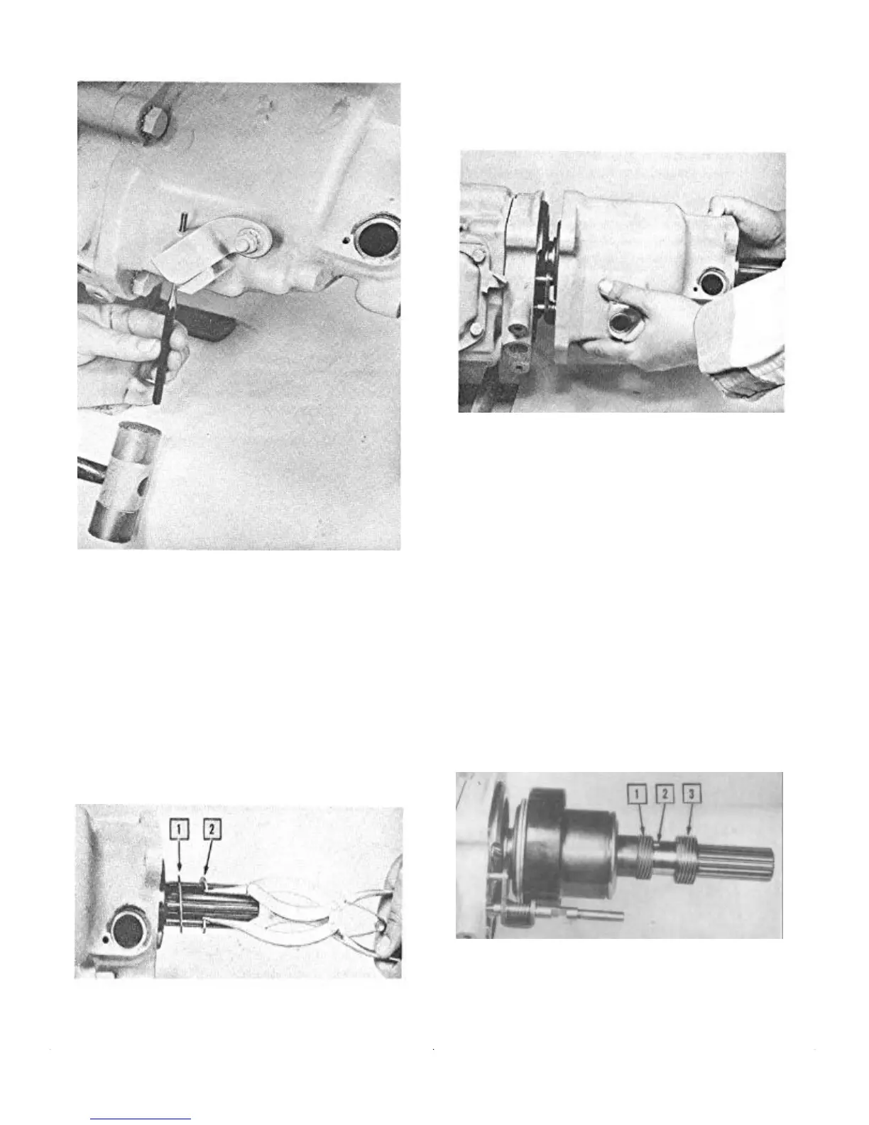
Removing Speedometer and Governor Drive Gears
The speedometer and governor drive gears which re-
mained on the overdrive main shaft are retained by a
Woodruff Key (Fig. 8). Removal only involves sliding
them off the main shaft.
1. Governor Gear 3. Speedometer Gear
2. Woodruff Key
FIGURE 8—Removal of Governor and
Speedometer Drive Gears
 Loading...