TRANSMISSION—OVERDRIVE
29
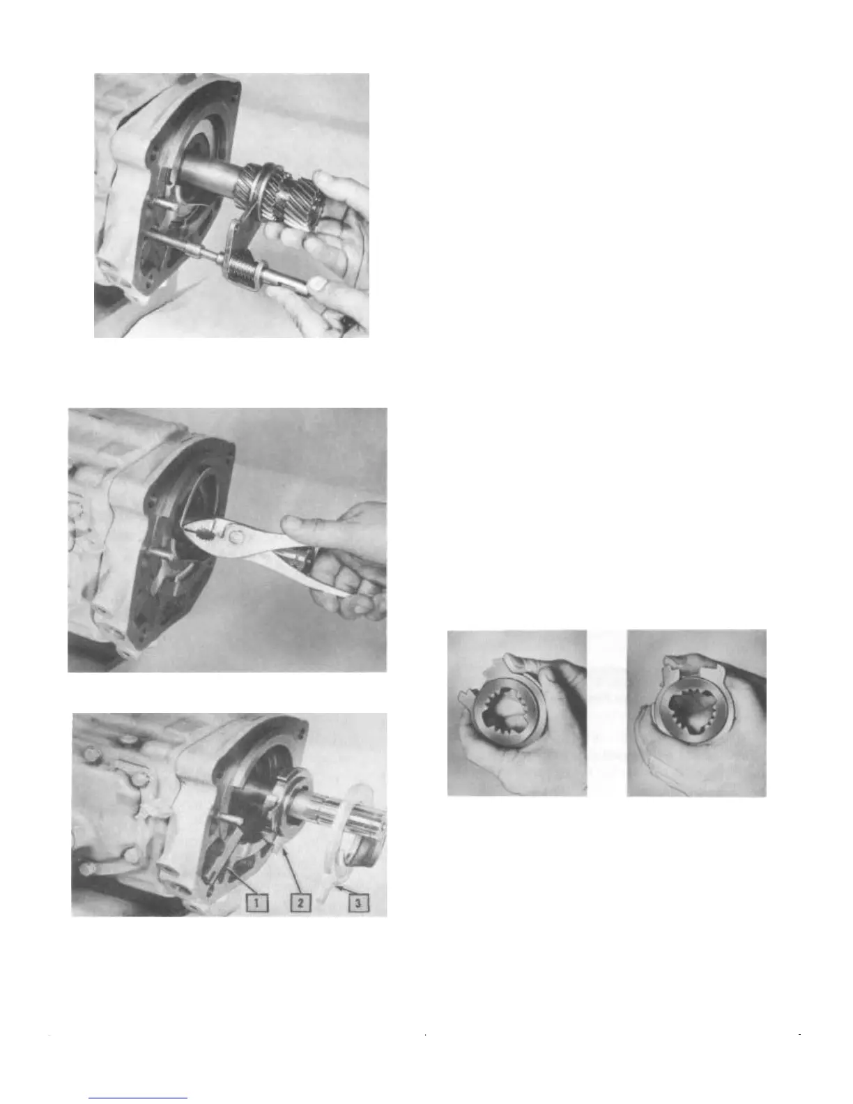
FIGURE 13—The Overdrive Shifter Rail
Assembly and the Sun Gear and Collar are
Removed Together
FIGURE 14—Removing Cover Plate Snap Ring
1. Locking Pawl 3. Cover Plate
2. Sun Gear Hub and Balk
Ring Assembly
FIGURE 15—Removing the Cover Plate Allows
the Sun Gear Hub Assembly and the Locking
Pawl to be Removed
Removing the Lockout Spring and Control Lever
If necessary, the control lever and shaft assembly may be
removed from the overdrive case. Discard the oil seal; a
new one will be used on reassembly. Remove the retract-
ing spring from the overdrive case.
INSPECTING PARTS
There are no internal adjustments to be made in the over-
drive. However, for assurance of good operation, every
part should be inspected carefully to be sure it is in good
condition. If all parts are up to standard and correctly
assembled, the unit will operate properly.
Pinion Cage and Gears
Examine the pinion gears in the planetary pinion cage for
worn, cracked, or chipped teeth. Rotate each gear to see
that it does not bind on the pinion shaft. Then examine the
oil slinger which is a part of the pinion cage. This slinger
supplies lubrication to the pinion gears. H it is bent or
otherwise damaged, it will not operate efficiently.
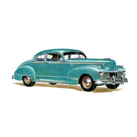
Sun Gear Hub and Balk Ring
Test the fit and tension of the balk ring on the sun gear hub.
When pressure is applied in a direction that tends to close
the ring, it should bind against the hub so that it will not
turn. When pressure is applied on the end of the ring in a
direction that tends to spread or open the ring, it should
slide around the hub (Fig 16).
A spring scale may be used to measure balk ring ten-
sion-3-1/2 to 5-1/2 pounds pull required (Fig. 17).
FIGURE 16—Testing Balk Ring Tension. Left:
When You Push One End Toward the Other,
the Ring Should Grab and Hold. Right:
When You Push One End of the Ring
Away from the Other, the Ring Should
Slide Around the Hub
Free Wheeling Rollers, Housing, and Cam
Examine each of the free wheeling rollers and the over-
drive main shaft housing in which they turn for wear,
scoring, rough surfaces, or any indications that the rollers
may be slipping in the housing. Inspect the roller cams on
the free wheel hub for wear or grooving (Fig. 18).