TRANSMISSION—OVERDRIVE
35
Install the free wheeling cam snap ring on the main
shaft. This snap ring is serviced in three different sizes
.063", .068", and .073". Select the thickest ring which will
fit into the retaining groove (Fig. 11). Proper selection of
the snap ring will reduce end play to a minimum.
Reinstalling the Ring Gear and Main Shaft
Replace the ring gear on the overdrive main shaft and lock
it in place with a snap ring (Fig. 10).
This ring is serviced in three different sizes .055",
.057", and .059". Select the thickest ring which will fit into
the retaining groove. Proper selection of the snap ring will
reduce end play to a minimum.
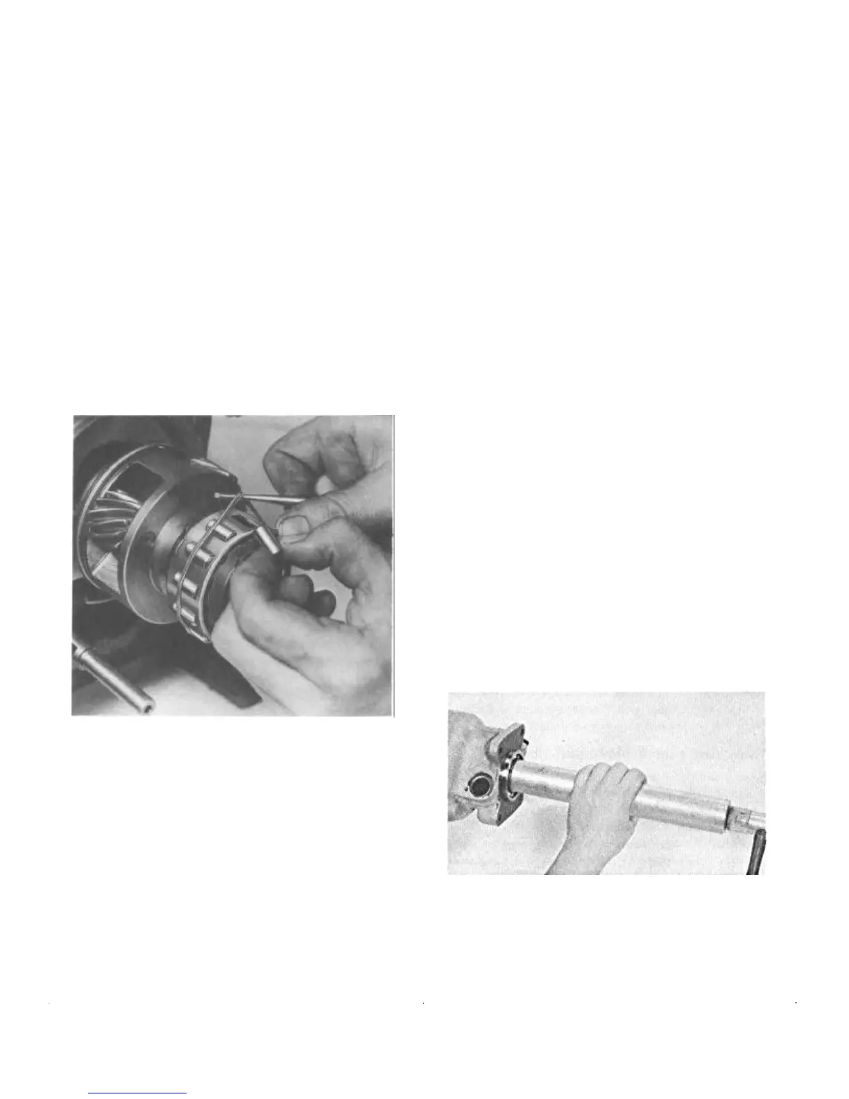
The Free Wheeling Rollers
Replace the free wheeling rollers in the free wheeling cam
retainer. A rubber band placed around the rollers will help
to keep the rollers from dropping out while the main shaft
and ring gear is being installed (Fig. 32).
FIGURE 32—A Rubber Band Serves to Hold
the Free Wheeling Rollers in Position
until the Ring Gear and Main
Shaft can be Installed
Now rotate the cage and roller assembly counterclock-
wise so that the rollers will be at the bottom of the cams.
This will permit the installation of the overdrive main shaft
and ring gear assembly.
Installing Speedometer and Governor Drive Gears
Insert the Woodruff Key into the main shaft. Then the
governor and speedometer drive gears. The governor drive
gear which is smaller in diameter is installed against the
shoulder on the main shaft.
NOTE: On a standard transmission, the speed-
ometer drive gear is retained in position by two
lock rings in addition to the Woodruff Key.
Reinstalling the Overdrive Case, Control
Lever, and Shift Shaft Assembly
Install the shift shaft oil seal and retractor spring in the
overdrive case.
Holding the bearing adapter to the transmission case
work the overdrive case onto the overdrive assembly.
Secure the assembly with the four attaching cap screws.
Push the shift shaft into the case so that the operating
cam will engage with the slot in the shift rod. Then install
the lock pin to hold the shaft in position.
NOTE: Inspect the operation of the shift lever
as follows: With the lever against the machined
stop on the boss of the case, a slight free move-
ment with no tension should be evident. Exces-
sive movement with no tension indicates that the
shift rod is binding in the case.
Installing Solenoid and Governor
Insert the solenoid plunger in the opening in the bearing
adapter and engage it with the notch in the locking pawl.
Turn the solenoid one-quarter turn counterclockwise to
lock the pawl and plunger together. Pull the solenoid to be
sure the plunger is locked with the pawl. Then tighten the
two cap screws.
Thread the governor unit into the overdrive case.
Tighten sufficiently to prevent oil leakage.
Reinstalling Rear Bearing, Oil Seal,
and Adapter
Install the rear bearing on the overdrive main shaft using
Tool J-2995 (Fig. 33).
FIGURE 33—Installing Rear Bearing
Install the rear spacer washer and snap ring (Fig 6).
NOTE: On the standard transmission, the rear
bearing is a press fit between the overdrive case
and torque tube and oil seal adapter.
 Loading...