34 TRANSMISSION—OVERDRIVE
Install the first and reverse sliding gear on the main shaft
with the shifting collar to the front.
Install the second speed gear on the main shaft with the
tapered cone to the front.
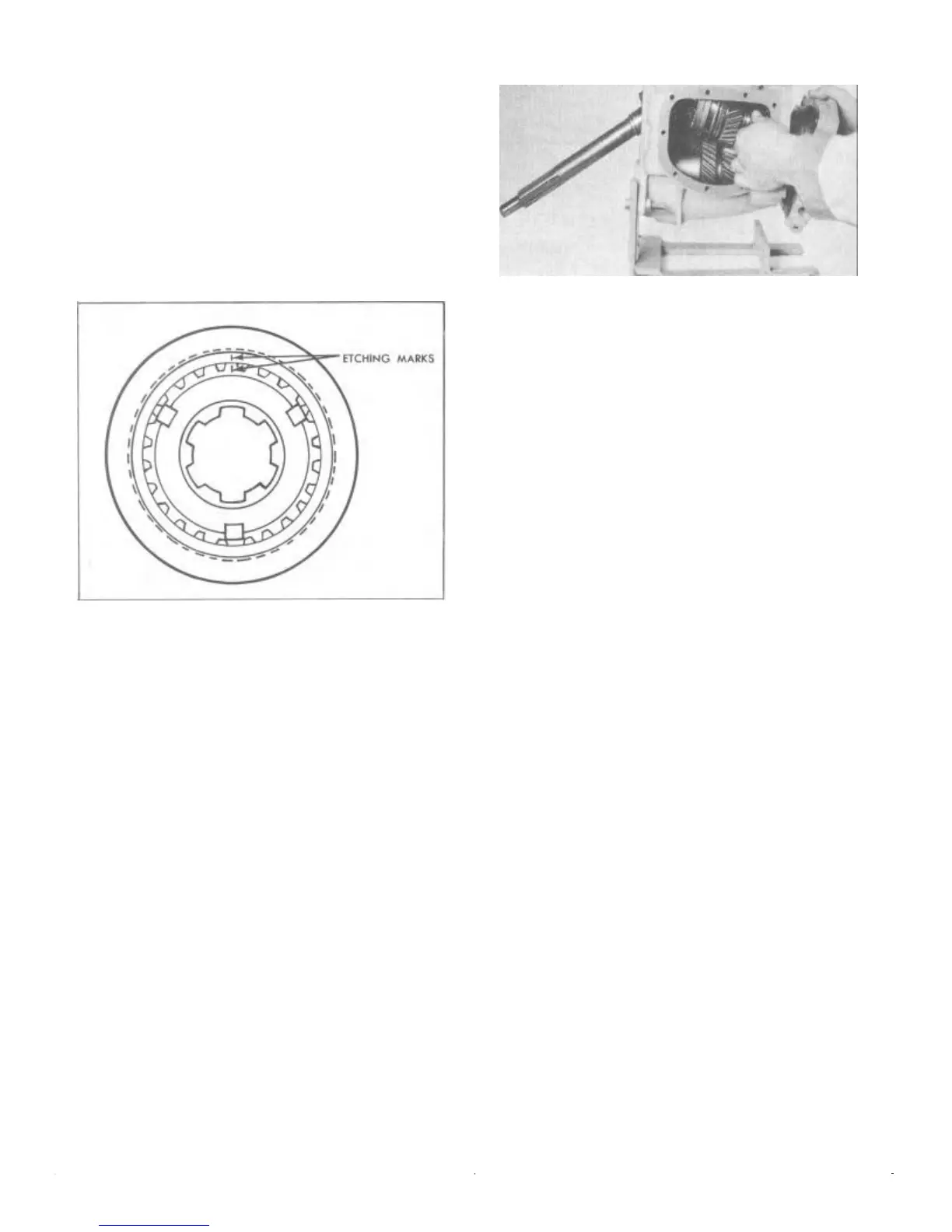
If the synchro-clutch was disassembled, check for
proper assembly. The hub section and the outer ring of the
synchro-clutch assembly are matched and lapped when
fabricated by the manufacturer and are marked according-
ly. The etching marks will correspond when properly
assembled (Fig. 30) . This will insure smooth sliding
action when shifting into second and third speeds.
FIGURE 30—Transmission Synchro-Clutch
Unit Etching Marks
Install the synchro-clutch including friction rings onto
the main shaft.
Install the lock ring and spacer washer on the main
shaft. Refer to Figure 25 for proper parts sequence.
Installing Clutch Shaft Assembly
Insert the fourteen clutch shaft needle bearings in the rear
of the clutch shaft. A coating of heavy lubricant will retain
them in proper position.
Insert the clutch shaft into the transmission case from
the rear. Position the shaft as shown in Figure 31.
Installing Main Shaft Assembly
Insert the main shaft assembly from the .rear of the trans-
mission case. It will be necessary to tilt the rear portion of
the assembly downward to provide the necessary clear-
ance to allow the synchro-clutch and second speed gear to
pass over the countershaft gear (Fig 31).
When the synchro-clutch just clears the countershaft
gear, place the clutch shaft in a horizontal position and
slide it onto the main shaft. Care must be taken to prevent
mislocation of the clutch shaft roller bearings. At that time,
place the clutch shaft and main shaft assembly in its proper
position in the transmission case.
FIGURE 31—Installing Main Shaft Assembly
Check the synchro-clutch friction rings for proper location
and freeness.
REASSEMBLING THE OVERDRIVE
When all parts have been carefully inspected the unit is
ready for reassembly. As each part is assembled, be sure it
is absolutely clean and lubricated with light engine oil.
Always use new gaskets, oil seals and snap rings in reas-
sembly.
Reinstalling the Hub and Balk Ring,
Locking Pawl, and Cover Plate
Install the hub and balk ring assembly with the chamfered
side of the ring against the sun gear hub.
Install the locking pawl, positioning the pawl and balk
ring in the "locked-out" position, with the pawl on the step
of the ring for correct installation of the solenoid.
Install the cover plate and trough in position and lock it
in place with the large snap ring.
This snap ring is serviced in three different sizes .0625",
.0665", and .0705". Select the thickest ring which will fit
into the retaining groove. Proper selection of the snap ring
will reduce end play to a minimum.
Reinstalling the Sun Gear and Shifter
Rod Assembly
Install the fork of the shifter rod in the sun gear shift collar.
Then hold them together as you slide the sun gear onto the
main (spline) shaft and the shifter rod into the opening in
the bearing adapter (Fig. 13).
Reinstalling the Pinion Cage and Cam
Install the pinion cage lock ring on the main shaft (Fig. 12).
Install the pinion cage assembly on the main shaft being
careful not to distort the oil slinger. The pinion cage
pinions mesh with the sun gear and the cage will butt up
against the lock ring previously installed.
Position the free wheeling cam on the main shaft so that
the counter bore of cam slides over the machined surface
of the pinion cage.
 Loading...