TRANSMISSION—OVERDRIVE
33
REASSEMBLY
When reassembling the transmission, always use new
gaskets and oil seals.
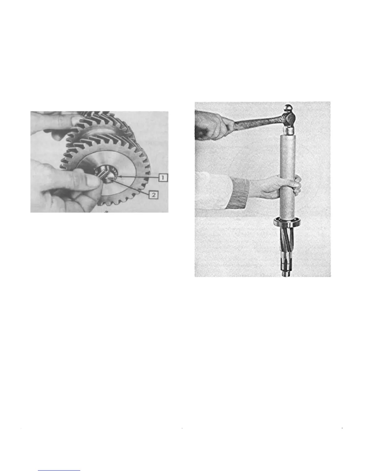
Reinstalling the Countershaft Gear and
Shaft
To hold the countershaft needle bearings, spacer, and
washers in place while installing the countershaft gear, use
a dummy shaft machined to .870" x 8-1/16" (Fig. 28).
1. Needle Bearings 2 . Dummy Shaft
FIGURE 28—Reassembly Countershaft
Gear Needle Bearings
After installing the bearings in the countershaft gear
and holding it in such a manner so as not to drop the
dummy shaft, install the thrust washers. The two small
projections on the face of the bronze rear thrust washer
must index with the grooves in the countershaft gear. The
front bronze thrust washer must index with the transmis-
sion case. Position the large thrust washer and install the
assembly in the bottom of the case.
Reinstalling the Reverse Idler Gear
Install the reverse idler gear with the chamfered side of the
teeth to the front of the ease.
Align the gear and install the reverse idler gear shaft
from the rear of the case. The shaft is a press fit into the
case, therefore, care must be taken to prevent damage to
the shaft. Install and align the Woodruff Key into the shaft
prior to driving the shaft flush to the rear face of the case.
Lift and properly align the countershaft gear. Prior to
installing the shaft, check the front and rear thrust washers
for proper alignment. The countershaft is a press fit into
the transmission case,
the transmission case, therefore, care must be taken to
prevent damage to the shaft. Install and align the Woodruff
Key prior to driving the shaft flush to the rear face of the
case.
Assembling Main Shaft Assembly
Install the transmission center bearing on the main shaft
using Tool J-2995 (Fig. 29).
FIGURE 29—Installing Center Bearing on
Transmission Main Shaft
Install the main shaft snap ring. This snap ring is ser-
viced in four different sizes .087", .090", .093", and .096".
Select the thickest ring which will fit into the retaining
groove. Proper snap ring selection will reduce end play to
a minimum.
Place the oil baffle into the overdrive adapter housing
with concave side facing forward.
Tap the main shaft and center bearing assembly into the
housing.
Install the large snap ring into the retaining groove of
the adapter housing. This snap ring is serviced in five
different sizes, .088", .091", .094", .097", and .100". Select
the thickest ring which will fit into the retaining groove.
Proper snap ring selection will reduce end play to a mini-
mum.
 Loading...