39
FRONT SUSPENSION—
STEERING
FRONT SPRING REMOVAL
The front spring seats, upper and lower, have been designed
with an ear to accept a hook tool for removal. The tool kit is
available for use in service through the Field Parts Ware-
house.
The spring is removed by raising the rear end of the car
opposite from the side from which the front spring is to be
removed. Additional compression may be gained by leaning
on the fender over the spring.
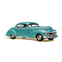
Install hooks, Kit Number 3200377, in the holes on the
ears of the spring seats. The hooks will hold the spring in a
compressed position to enable removal from the car (Fig. 1)
.
FIGURE 1—Spring Hooks Installed on Spring
Seat
A service spring replacement may be installed by using the
following procedure.
Install upper and lower cushions, upper and lower spring
seats on the spring. Align the holes in the ears of upper and
lower spring seats.
Compress the spring by suitable means, arbor press or
hydraulic jack and install hooks on spring seats. The spring
can then be installed on the front coil spring support. The
hooks are released from the spring seat by raising the oppo-
site rear end of the car.
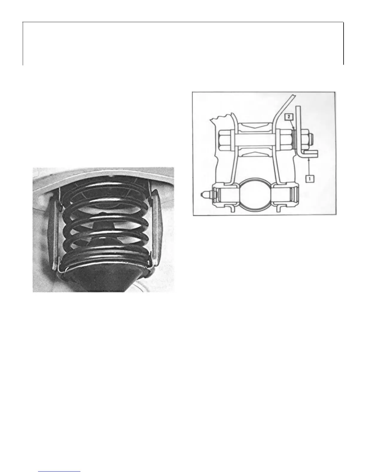
STEERING GEAR STOPS
All Automatic transmission equipped cars WITHOUT
POWER STEERING and all Standard and Overdrive Transmission
transmission equipped cars have the steering gear stops
located on the lower control arms (Fig. 2) .
1. Steering Gear Stop 2. Shims
FIGURE 2—Steering Gear Stops
Production location of the steering gear stops is provided
by installation of three 1/ 6" washer shims. In service, the
amount of shims may be varied to provide adequate wheel
turning radius and to prevent tires rubbing at any point when
wheels are in full turn, full bump position.
All Automatic transmission equipped cars WITH
POWER STEERING have adjustable steering stop screws
located on the pitman arm.
Tool J-1374 or J-5566 is used to remove the pitman arm.
It will be necessary to increase the depth of the opening 1/2"
to adapt the tool for use on cars equipped with power steer-
ing. Figure 4 illustrates the revision required.
STEERING KNUCKLE PIN AND SPINDLE
The upper control arm trunnion is provided with needle
bearings and a thrust bearing is retained by a castellated nut.
The steering knuckle pin is threaded into the lower control
arm trunnion.
At time of assembly; screw the steering knuckle pin into
the lower trunnion until it is bottomed; then unscrew it one
turn. This will provide approximately 1/4" clearance be-
tween the shoulder on the knuckle pin and the trunnion. The
knuckle pin installed in this manner will prevent
"bottoming" on extreme turns and insure maximum bearing
on the thread area.

 Loading...