Installation Manual 3000B Page 2 of 9 May 2012
Long T-Handle Allen Wrench Set (3/16” to 3/8”)
Medium Size Flat Head Screw Driver
Brass Ball Peen Hammer
Flat Bastard File
240 Grit Sand Paper
Anti-Seize Lubricant
WD-40
12” Crescent Wrench
Shop Towels
Exact-A-Pitch
®
Digital Protractor (P/N 62375)
25 ft. Measuring Tape
Pencil or Marker
Open/Box End Wrench Set (1/2” – 1-1/2”)
Socket Set for 1/2” Drive (1/2” – 1-1/2”)
Torque Wrench(s) Rated for 0-200 ft-lb
Retainer Ring Tool (Hudson Provided)
RECOMMENDED TOOLS
INSTALLATION PROCEDURES
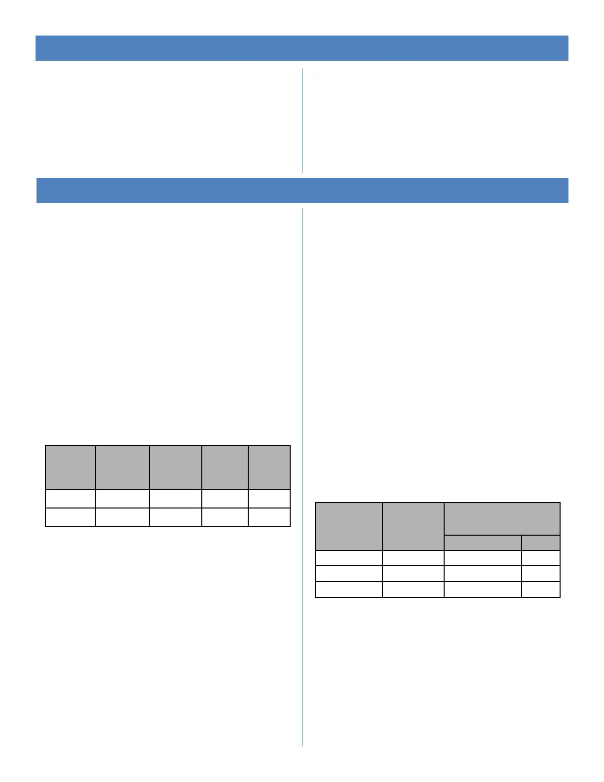
Bushing
Size
Allen
Wrench
Size
Cap
Screw
Size
Socket
Size
Torque
(ft-lb)
Dry
Q2 - 3/8” 9/16” 29
R2 3/16” 3/8” 9/16” 29
Cap Screw
Size
Socket
Size
Torque Value
(ft-lb)
Lubricated Dry
5/8” NC 15/16” 70 90
3/4” NC 1-1/8” 125 130
1” NC 1-1/2” 150 160
ASSEMBLY WITH BUSHING
Clean all mating surfaces between hub, bushing and shaft. All
grease and lubricant should be removed, leaving the mating
surfaces dry.
If there is no shoulder on shaft to prevent bushing from sliding
down shaft, slide spacer/sleeve (not provided) on shaft before
bushing or use a thrust retainer (optional equipment) on top of
hub. Slide bushing and key onto shaft until flush with end of
shaft. The shaft size determines the bushing type (Q2 or R2).
Lock bushing on shaft by tightening the set screw in flange
with an Allen Wrench. (Note: Q2 bushings have no set screws.)
Line up key and set hub on bushing. Engage the three (3) cap
screws in flange of bushing into hub spool, using a torque
wrench with a socket, and tighten evenly. Use the following
table to determine the proper tools and torque values.
ASSEMBLY WITH STRAIGHT SHAFT
(NO BUSHING)
Clean all mating surfaces between the hub and the shaft. If
there is no shoulder on shaft to prevent hub from sliding down
shaft, slide spacer/sleeve (not provided) on shaft before hub or
use a thrust retainer (optional equipment) on top of hub. Install
key in shaft. Line up key and keyway and set hub on shaft.
Tighten set screw(s) in hub.
ASSEMBLY WITH TAPERED SHAFT
(NO BUSHING REQUIRED)
Clean all mating surfaces between the hub and shaft. Coat all
mating surfaces with an anti-seize or lubricating compound.
Align keyways and install hub. Install retainer plate and cap
screw(s) with lock washer(s). Shaft size determines what size
cap screw is necessary. Using a torque wrench with a socket,
evenly tighten cap screw to recommended standard per table
below.
NOTE: Retaining arrangement varies with gear shaft design.
 Loading...