Installation Manual 3000B Page 5 of 9 May 2012
SET PITCH AND TRACK
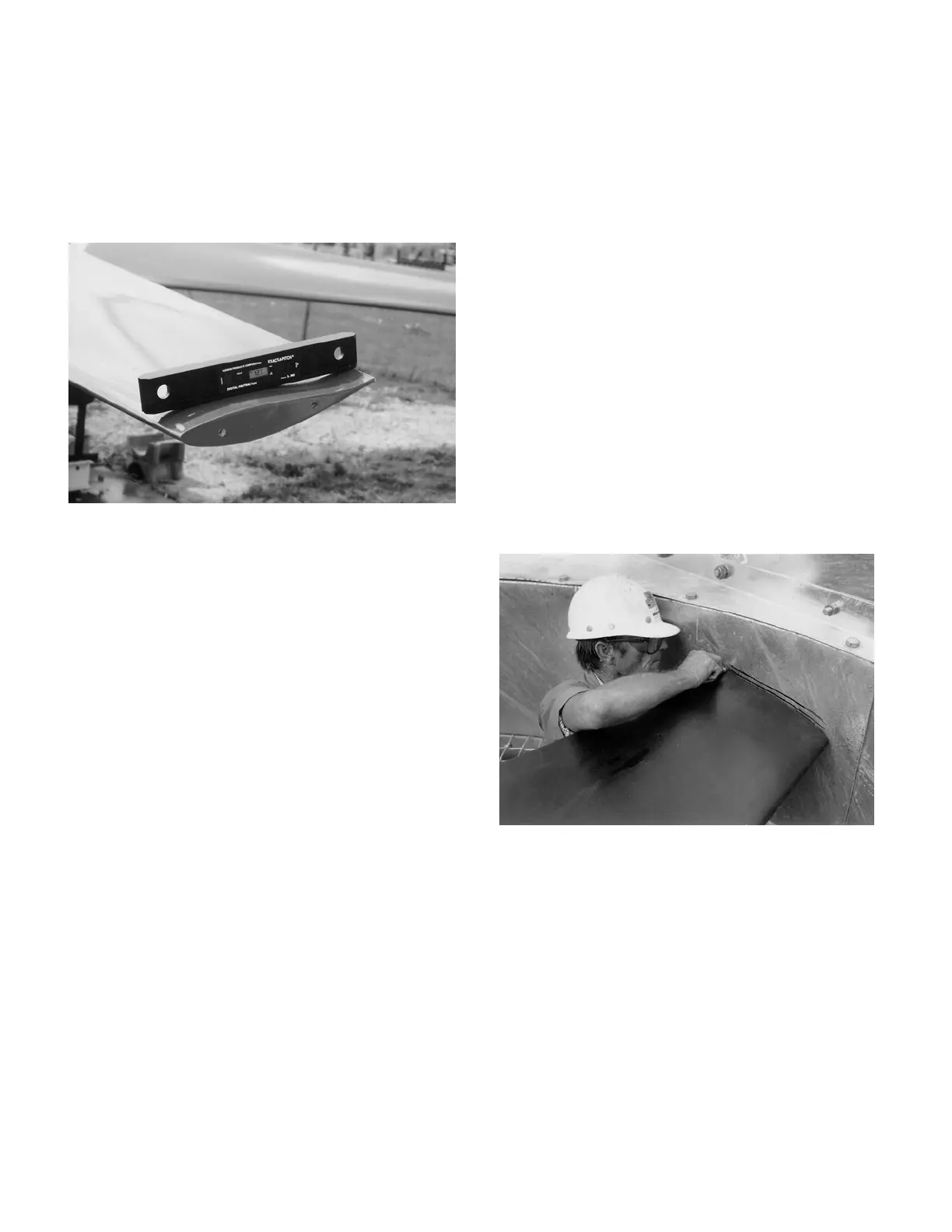
Use Hudson’s EXACT-A-PITCH
®
digital protractor (See Figure
6) or a bubble protractor to set blade pitch. Mount protractor on a
flat bar as a base and place it approximately 1” from tip of blade.
Note pitch on protractor. Rotate fan 360
º
, noting high and low
pitch readings. Locate place where pitch reading is at mid-point
between high and low readings, and set pitch at that point.
Rotate blade in socket until digital protractor shows specified
pitch angle to within +/-0.2
º
. Fan pitch angle is shown on fan
specification sheet for design duty. After desired pitch angle is
set, raise and lower end of fan blade and find mid-point of blade
travel. Hold blade at the mid-point and pull blade outward so it
sits against retainer rings.
Check to see that blade retainer rings are properly seated in both
hub and blades grooves. It may be necessary to back cap screws
off about one turn and re-tighten them in order to force ring to fit
properly in groove.
Start tightening the four blade socket cap screws by alternating
the sequence of tightening (like tightening lug nuts on a car
wheel). The torque applied to any one cap screw shall be no
more than 5 ft-lb, greater than the torque on any of the other (3)
cap screws during the tightening process. All cap screws are to
be tightened to 15-20 ft-lb. Make sure shoulder on blade neck fits
tightly into and against retainer ring. DO NOT OVERTIGHTEN
CAP SCREWS. After cap screws are tight, tighten jam nuts
against socket to 15-20 ft-lb.
Note B: If a severe duty retainer (SDR, Figure 5A) is used, it
may be necessary to loosen the SDR fasteners as necessary for
proper retainer ring seating at the outset. See cap screws labeled
as (3) in Figure 5B or 5C.
Figure 6
When bolts are tightened, hold a pencil against top end of blade
and mark the level onto a fixed object, such as a pole or the fan
ring.
Install remaining blades at same place as first blade, following
the instructions above. After tightening cap screws, mark top
end of each blade in same place first blade was marked. If
marks differ by more than 3/4”, adjust blade.
Note C: It is more important to positively seat the retainer ring
pair into the blade shank ring groove than to achieve perfectly
consistent tracking between all blades. If there is a conflict in
achieving both blade seating and blade tracking, ignore the
tracking specification.
CHECK TRACK
After fan is installed in fan stack cylinder ring, outline the top
side of each blade onto fan stack cylinder ring with a marker
(See Figure 7). The difference between levels of highest and
lowest outlines should not be more than 3/4”. To raise blade
track, loosen blade socket cap screws on top half of socket and
tighten cap screws on bottom half. To lower blade track, loosen
bottom screws and tighten top ones. Tighten 3/8” cap screws to
15-20 ft-lb torque. Re-tighten jam nuts after adjustment.
Note D: It is more important to positively seat the retainer
ring pair into the blade shank ring groove than to achieve
perfectly consistent tracking between all blades. If there is a
conflict in achieving both blade seating and blade tracking,
ignore the tracking specification.
Figure 7
 Loading...