10
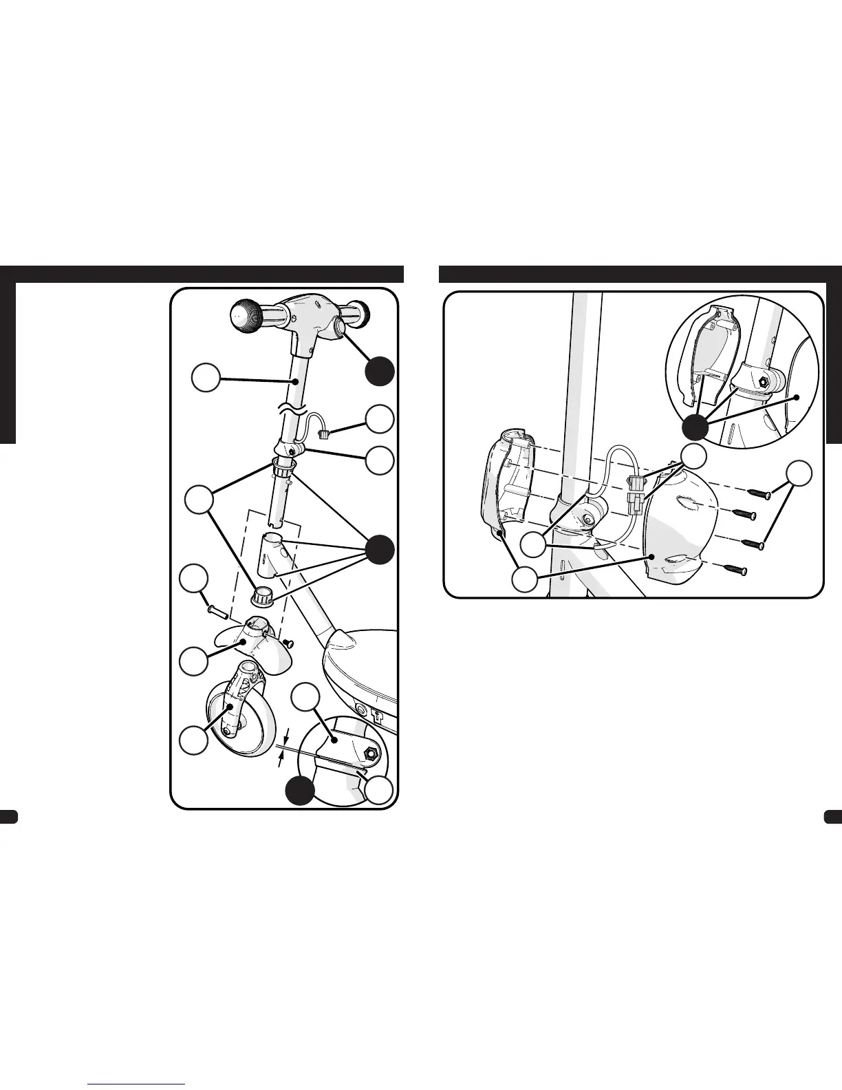
Assembly
STEPS:
1. Ensure Power Button
A
and
Wiring Connector
B
are
facing BACK.
2. Insert Steering Rod
C
down
through Neck frame.
3. Ensure top and bottom Neck
Bushings
D
are fully inserted
into Neck frame and sit fully in
Notches
E
.
4. Place Fender
F
over Fork
Assembly
G
.
5. Insert this Fork Assembly up
onto Steering Rod
C
fully so
that Fork mounting holes line
up.
6. Install Fork Screw Set
H
through Fork assembly and
Steering Rod. Tighten securely.
7. With Front Wheel on the
ground, tighten Clamp
I
securely.
NOTE: Ensure there is approx.
1/16” gap between Clamp
I
and
top Bushing
D
as shown in view
J
.
NOTE: Ensure Handlebar turns
freely from left to right until it hits
the turn stops.
Assembling the Front Wheel and Handlebar:
D
E
J
H
F
G
D
I
B
I
C
A
1/6”
(3mm)
PROCEED TO NEXT STEP >>
11
Handlebar Connectors and Clamp Cover Assembly:
Assembly
STEPS: (TIP: Hand start screws
D
before assembly)
1. Connect Power Plugs
A
rmly and completely.
2. Tuck excess wire into Wire Slots
B
- Check that Handlebar and fork turn fully from
left to right and that Wires are not pinched or stretched.
3. Place Clamp Covers
C
around Steering Tube Clamp
NOTE: Ensure Clamp Supports t INSIDE Clamp gap as shown in view
E
.
4. Install 4 Screws
D
securely - Ensure Connector Wires are not pinched.
NOTE: Make sure Handlebar and Fork turn easily and completely from left to right.
C
A
D
B
E