EasyManua.ls Logo

Humanscale M10 User Manual

Humanscale M10
2 pages
To Next Page IconTo Next Page
Page #1 background imageLoading...
Page #1 background image
Desk Mount
Installation Instructions
GT-NPD-IM-826-001
© 2019 Humanscale Corporation. The text and artwork are copyrighted materials.
All rights reserved. The Humanscale mark and logo are trademarks of Humanscale Corporation
and are registered in the United States and certain other countries. The M10 trademark is
owned by Humanscale Corporation.
M10 INSTALLATION HARDWARE
4mm Hex Key 3 Crossbar Link Screws
4 Plastic Spacers4 Standard VESA Bracket Screws
4 Extended VESA Bracket Screws
5mm Hex Key
VESA Bracket and Cover
NOTE: 4mm and 5mm Hex Key can be
found under the plastic base cover.
8mm Hex Key Bolt-Through Plate Bolt-Through Bolts
Bolt-Through Mount
Crossbar Installation Hardware
Clamp Mount
Sliding Desk Mount
For our terms and conditions please go to
https://www.humanscale.com/about/legal-information/terms-conditions.cfm
STEP 9: CABLE MANAGEMENT
1. If using multiple monitors, rst route the cables through the plastic cable clips on
the front of the crossbar. If using a single monitor, skip to step 2.
6. Slide the cover down the arm to lock in
place, then gently pull the cables
through the arm to remove excess slack.
5. Lift the cover and cables up to the lower
link, making sure that the cover sits
ush with the surface of the arm.
4. Using the two cutouts (D) as guides, run
the cables over the lower link cover.
3. Slide the plastic cover (C) on the lower
link upward to remove.
2. Route power and monitor cables
through the exible cable clips on the
M8.1’s upper link (B).
NOTE: Leave enough slack in the cables
to allow arms to rotate without difculty.
CAUTION: Don’t insert extension cords.
Don’t insert any cord connecting one
workstation to another.
B
C
D
A
STEP 8: WEIGHT ADJUSTMENT
A
C
E
D
Your monitor should move up and down easily and stay in place once adjusted. If it is
difcult to adjust or moves without assistance, it is not properly counterbalanced.
M10 Arm - Total Weight Range: 20-48 lbs. (9-21.7 kg)
Single Monitor - Max weight: 48 lbs. (21.7 kg)
Dual Crossbar - Max weight per monitor: 22.5 lbs. (10.2 kg)
Triple Crossbar - Max weight per monitor: 10 lbs. (4.5 kg)
1. To access the Adjustment Screw (E), use your nger to pry open the Cover (D) on
the Upper Arm Link (C).
2. Using the 5mm Hex Key turn the Adjustment Screw (S) clockwise to INCREASE the
load tension, and counter-clockwise to DECREASE the load tension. Turn the
Adjustment Screw (E) until the Monitor is properly balanced.
3. Move the monitor around to ensure that the motion is smooth and the arm functions
as intended and holds the monitor in place.
5. Reposition the Cover (D) and press until it snaps into place.
CAUTION: Do not overtighten the screws as it can damage the screw head or threads.

Other manuals for Humanscale M10

Question and Answer IconNeed help?

Do you have a question about the Humanscale M10 and is the answer not in the manual?

Humanscale M10 Specifications

General IconGeneral
BrandHumanscale
ModelM10
CategoryRacks & Stands
LanguageEnglish

Summary

Weight Adjustment for Monitor Balance

Adjusting Load Tension

Instructions on using the 5mm Hex Key to increase or decrease load tension for proper monitor balance.

Overtightening Warning

Caution against overtightening screws to avoid damage to screw heads or threads.

Cable Management Procedure

Cable Routing Guide

Guide to route cables through plastic clips on the crossbar and flexible clips on the arm.

Extension Cord Restriction

Warning not to insert extension cords or cords connecting different workstations.

M10 Installation Hardware Overview

Hardware Components List

Identifies various screws, spacers, hex keys, and brackets included for installation.

Mounting to Work Surface

Clamp Mount Installation

Details on attaching the clamp mount to the work surface edge or against a wall.

Bolt-Through Mount Installation

Instructions for installing the bolt-through mount using a hole in the work surface.

Sliding Desk Mount Installation

Procedure for installing the sliding desk mount with minimal clamp clearance.

Smart Stop Adjustment

Smart Stop Ring Configuration

How to adjust the Smart Stop Ring to limit the arm's range of motion (90°, 180°, 360°).

Arm to Base Stem Attachment

Linking Arm Components

Instructions for connecting arm links, including dynamic and angled links.

VESA Bracket Installation

Attaching VESA Bracket to Monitor

Procedure for separating the VESA cover and attaching the bracket to the monitor.

Monitor Attachment to Arm

Securing Monitor to Arm

Steps for lowering the monitor onto the arm and securing it with the quick release tab.

Crossbar Attachment for Dual Monitors

Crossbar to Link Connection

How to attach the crossbar to the crossbar link using specific screws.

Optional Handle Attachment

Guidance on attaching and adjusting an optional handle to the crossbar.

Monitor Leveling Adjustment

Fine-tuning Monitor Height

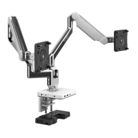
Using the adjustment screw to align the height of dual monitors.

Related product manuals