4
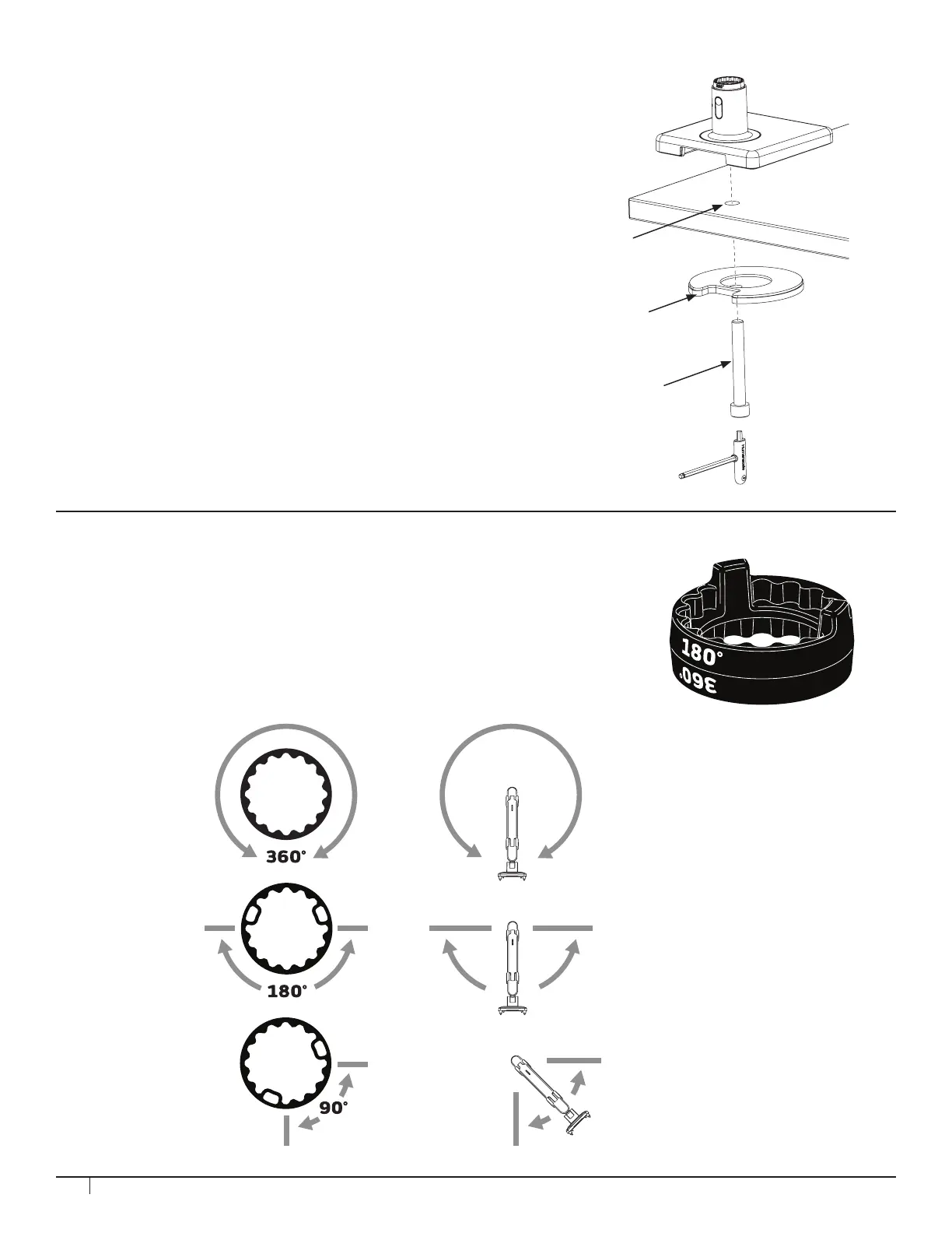
BOLT-THROUGH MOUNT
1. Drill 1/2” hole through work surface in desired location.
NOTE: Bolt-Through Mount can accommodate a hole up to 4” (102mm)
in diameter. If hole is 2” (51mm) or more, cables can be routed through
the hole. For some 2” grommet holes, cables should be routed before
installation of mount to accommodate cable plugs (cable access is
approximately 1.5” x 0.25” with 2” grommets).
2. Position the M2.1 Base over the work surface hole (J).
3. Align Bolt-Through Plate (K), foam side up, under the work surface.
Pass the Bolt (L) through the hole in the plate and screw into M2.1
base by using 8mm hex key.
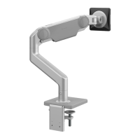
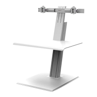
In each arm connection, there is an adjustable Smart Stop Ring which can be
positioned to limit the arm’s range of motion. Depending on the orientation of the
ring the arms can be set to rotate either 90°, 180° or 360°. The marked angle will
be in the center of the range of motion. The stop rings must be congured in such
a way that the dynamic link head does not pass behind the rear edge of the unit.
Arm can rotate
without stopping
Arm can rotate 180˚
Arm can rotate 90˚
STEP 2: SMART STOP ADJUSTMENT
J
L
K