Container transport (option)
192
Operation: body
5
General
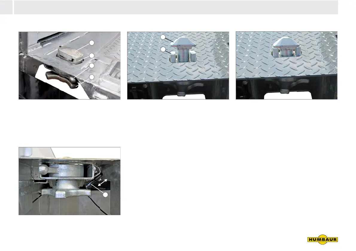
Fig. 155 “Twist-Lock” overview
1 Pivot pin
2 Guide bush
3 Grooved bush
4 Clamping nut
5 Safety locking mechanism
Fig. 156 “Twist-Lock” overview
Locking point extended
Fig. 157 Locking point extended
1 Pivot pin
2 Guide bush
Raise the safety locking mechanism
(Fig. 156/5) and secure it.
Unscrew the clamping nuts
(Fig. 155/4).
Turn the grooved bush (Fig. 155/3) to
the right.
Raise and rotate the clamping nuts
and the pivot pin (Fig. 157/1)
simultaneously.
The guide bush (Fig. 157/2) comes
out the top.
Tighten the clamping nut.
Secure the clamping nuts using the
safety device.
Fig. 158 Locking point in intake position
The pivot pin lays on the guide bushes
(see Fig. 158).
The container can be set down or
removed.
Check that all locking points are
extended before setting down the
container.
A - 102
1
2
3
4
A - 243
5
A - 104
1
2
A - 105


 To Next Page