Operation: chassis
97
Swivel support (option)
1
2
3
4
5
6
7
8
Operating the swivel support
Unlocking
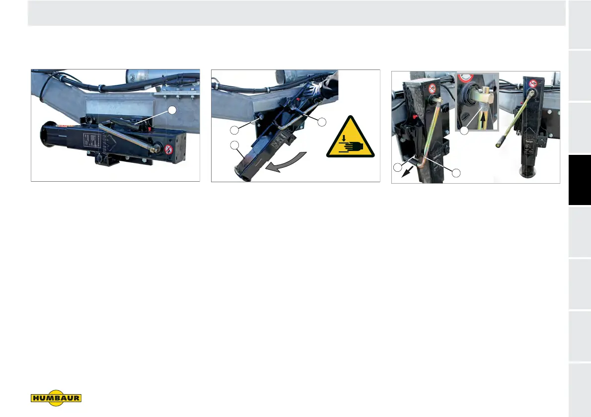
Fig. 49 Swivel support / drive position
1 Locking lever, engaged
Pull the locking lever (Fig. 49/1)
towards you.
The pin extends from the locating
hole.
The swivel support is enabled.
Rotating
Fig. 50 Turning the swivel support
1 Swivel support
2 Locating hole
3 Locking lever, unlocked
Turn the swivel support (Fig. 50/1) into
the vertical support position.
Swing the locking lever (Fig. 50/3)
downwards.
The pin retracts into the locating hole
(Fig. 50/2).
The swivel support is secured.
Unlocking the hand crank
Fig. 51 Swivel support - support position
1 Retaining plate
2 Hand crank
3 Compression spring
Pull the hand crank (Fig. 51/2) out of
the retaining plate (Fig. 51/1).
Press against the compression spring
(Fig. 51/3) and turn the hand crank so
that the handle points forwards.
The hand crank is unlocked.
F-050
1
1
2
3
1
2
3
 Loading...