www.HunterFan.com
1.888.830.1326
Model #99120
Universal Wall
Mount Control
Getting Started
Wiring the Receiver Wiring the Wall Control
OR OR OR
Remove the canopy. If uncertain how
to remove it, reference the fan’s owner’s
manual. With wiring exposed, it may be
helpful to note existing wire connections
or take a digital photo for reference.
Remove the wire connectors that connect
the wires from the outlet box to the fan,
leaving the grounding wires connected.
CONNECT WIRES FROM
RECEIVER TO FAN - Using
the orange wire connectors,
connect the blue wire from
the receiver to the blue wire
(or possibly black with white
stripe wire) from the fan.
Connect the yellow wire from
the receiver to the black wire
from the fan.
If you are uncertain about
wire colors or connections,
please contact a qualied
electrician.
CONNECT WIRES FROM
RECEIVER AND FAN TO
WIRES FROM OUTLET
BOX - Using the orange wire
connectors, connect the
black wire (ungrounded)
from the ceiling to the black
wire from the receiver.
Connect the white wire
(grounded) from the ceiling
to both the white wire from
the receiver and the white
wire from the fan.
AFTER ALL WIRES ARE
CONNECTED and secured
with wire connectors,
re-install the canopy.
Before installing the Universal
Remote Control Receiver,
use the pull chains to set the
fan speed to HIGH and the
light to ON. Be sure power is
OFF before proceeding with
installation.
Choose the hanging system that most closely resembles the one used by your fan and install the receiver as shown and wire as directed.
Note: Some fans may have considerable excess lead wire. For easier canopy installation, cut the excess wire, leaving a minimum of 8” remaining. Re-strip the fan lead wires 1/2”. Place remaining excess wire into
the ceiling electrical box. The bracket and fan must remain properly grounded.
You may have installation issues if the fan is installed on an angled ceiling. For assistance, call 1-888-830-1326.
Turn the splices upward and push them carefully back through the hanger bracket
into the outlet box. Spread the wires apart, with the grounded wires on one side of
the outlet box and the ungrounded wires on the other side of the outlet box.
To avoid possible electrical shock, before installing or servicing your fan, disconnect the power by turning off
the circuit breakers to the outlet box and associated wall switch location. If you cannot lock the circuit breakers
in the off position, securely fasten a prominent warning device, such as a tag, to the service panel.
M0061-01 • 01/16/14 • © Hunter Fan Company
F
R
O
M
R
E
C
E
I
V
E
R
black
blue
yellow
blue (light out)
F
R
O
M
F
A
N
F
R
O
M
C
E
I
L
I
N
G
black (ungrounded)
white (grounded)
white
black
Turn Power
OFF
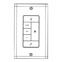
After removing the switch plate
cover, remove all wiring from
the switch.
Using orange wire connectors,
connect the two black wires
(ungrounded) from the outlet
box. Also connect the two green
or bare wires (grounding) from
the outlet box with the grounding
wire from the wall control.
Insert the wall control into
the outlet box and secure the
two screws using a Phillips
head screwdriver.
Install the cover plate using a
Phillips Head screwdriver to
secure the two cover plate screws.
If you are installing multiple remote-controlled fans
on the same circuit breaker,
you may need to perform a few extra steps to prevent interference
or faulty operation of your remote controls.
Go to www.HunterFan.com/FAQs and click “How do I properly
install multiple remote-controlled fans?” for more information.
F
R
O
M
R
E
C
E
I
V
E
R
F
R
O
M
F
A
N
white