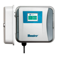
Connecting Your
Hydrawise Flow Meter
Thank you for purchasing a Hydrawise flow meter.
There are a few simple rules to follow to ensure that your
flow meter will give faultless service.
On the rear of this page you will find a Hydrawise
connection diagram and further helpful information is
available online at http://hydrawise.com/support.
Contents
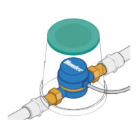
The flow meter consists of 2 parts –
! Flow meter body
The flow meter body contains an analog dial for
manual readings as follows –
Your flow meter will have 3 wires protruding from the
flow meter’s body.
The wires need to be connected to the Sensor
inputs on the controller for remote measurement.
In all models only 2 wires are used.
" Adapter
Each flow meter has an optional adapter to allow
connection to smaller diameter pipes.
Planning
Planning is an important step in the successful installation
of your Hydrawise flow meter and the reliable operation of
your irrigation system.
! Flow meter location
Flow meters are installed between the water supply
and the master valve. To avoid false alerts, there
should be no water taps or other uncontrolled water
use on the downstream side of the flow meter.
Where all the solenoids connected to the controller
are not grouped together, it may be necessary to
install more than one flow meter.
Where the flow meter is installed, do not have 90
degree bends within approximately 12 inches
(300mm) either side of flow meter.
" Cable
Two wire cable will be required.
The gauge of flow meter cable will be determined by
the total length of cable between the controller and
the flow meter. The general rule here is 0.5mm
(24GA) wire is good for a run of up to 240 feet (80
metres).
Installing
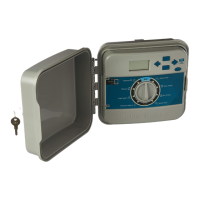
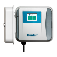
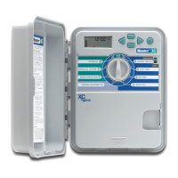
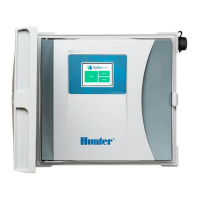
The following instructions assume you have already
installed your Hydrawise controller.
! Flow meter body
The flow meter has a marking on the body indicating
direction of water flow.
Installation of the flow meter must be in the correct
orientation with water flowing in the direction of the
arrow on the flow meter body.
" Connect flow meter wire
# Hydrawise strongly recommends that all flow
meter connections be soldered and sealed
against moisture for reliable, long term
operation.
Connect the wires as follows to your Hydrawise
controller –