8 English
Demounting Tires from RimDemounting Tires from Rim
If the wheel has a TPMS sensors installed, keep the sensor
under the upper roller when inserting tool head. This will prevent
the tool head from contacting the sensor. Refer to decal for
proper TPMS placement before demount.
Lower tool head into position such that a small gap remains above the
SmartSet indicator notch (shown in image 7. Decal: 128-1944-2).
Image 6.
With the upper roller pressing down on the tire, bring your tool head down
insert in between the bead and the rim, rotate tire while doing so to ease
tension.
Image 7.
Recommended tool head height
DO NOT ROTATE while raising the tool hook. Ensure tool
head cradles the rim edge before rotating during demount
of upper bead.
MaintenanceMaintenance
Maintenance ScheduleMaintenance Schedule
Do not hose down or power wash the tire changer.
Proper care and maintenance are necessary to ensure that the tire changer
operates properly. Proper care will also ensure that rims and tires are not
damaged during the mount/demount process.
Maintenance
Schedule
Perform the Following Maintenance
Daily Turn the tire changer power off at the end of the work
day. At a minimum, depress the emergency stop
switch. Never leave a wheel assembly on the tire
changer overnight. Always remove all assemblies
and ensure tools are returned to their home position.
Check for worn or damaged rubber and nylon
components that should be replaced to prevent
damage from occurring. Replace worn parts as
needed (rubber pads and blocks, rollers, and mount/
demount head). Clean all areas that contact rims or
tires to prevent possible scratching to rim.
Weekly Clean the tire changer with shop towels or a vacuum
cleaner. Do not clean with or use compressed air,
which can blast dirt between moving parts. Do not
use cleaning solvents to clean pressure regulator/
oiler.
Annually Change hydraulic fluid and filter once per year.
Contact your Hunter Service Representative for this
service.
Periodically Check for loose bolts and tighten per specifications.
Contact your Hunter Service Representative for
information.
Warranty Information Warranty Information
Hunter Engineering Company warrants new equipment to be free from defects
in material and workmanship under normal conditions of use for a period of
three (3) years from the date of installation. Exceptions to this warranty are
listed below:
• Field labor is covered under this warranty for a period of six (6) months.
• ADASLinkTM units carry a one (1) year warranty and remain under
warranty as long as a subscription is maintained there after.
• DAS 3000 units, including electronic circuit boards, carry a one (1) year
warranty.
• Printers carry a one (1) year warranty.
• Normal consumables and wear items are not covered. Exception is
batteries, which are warranted for a period of six (6) months.
• Product that has been subject to abuse, misuse, alterations, accident,
exposure to the elements, tampering, unreasonable use, or not
maintained in a reasonable or necessary manner.
• Replacement parts purchased through the Hunter Service Center and
no longer covered by machine warranty are warranted for a period of six
(6) months.
Explanation of SymbolsExplanation of Symbols
These symbols may appear on the equipment.
Alternating current.
Earth ground terminal.
Protective conductor terminal.
l
ON / OFF (Supply) condition
Risk of electrical shock.
Stand-by switch.
Not intended for connection to public
telecommunications network.
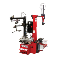
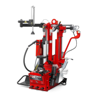
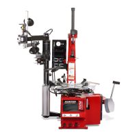
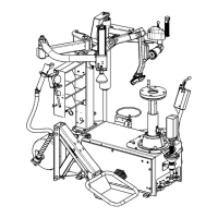
Equipment Component DiagramEquipment Component Diagram
Image 3.
A) Leverless Tool Head B) Bead Press Arm
C) Mount/Demount Rollers D) Quick Clamp
E) Wheel Support Plate F) Wheel Lift Platform
G) Control Console H) Blast Inflator Nozzle
I) Storage Cabin J) Tire Rotation Pedal
K) Wheel Lift Pedal L) Wheel Lift Pedal Assembly
Basic OperationBasic Operation
Control Console DiagramControl Console Diagram
Image 4.
A) Emergency Start/Stop
B) Tool Head Adjustment
Push up to raise Tool Arm
Push down to lower Tool Arm
Push left (green) to lower hook
Push right (yellow) to raise hook
C) Push + to increase pressure
Push - to decrease pressure
D) Auto inflate button
To begin auto inflate sequence, push once max pressure: 2.8 Bar (40
psi)
E) Wheel Size Adjustment
Moves wheel support stand out or in
Push Left (out) for larger wheels
Push Right (in) for smaller wheels
F) Upper Roller Arm
Lower Roller Arm
Push up to raise Arms
Push down to lower Arms
Push left to indent, right to unindent
indent travel is fixed at 19.05 mm (0.75 inch)
G) Metric option
H) Manual psi ajustment
press + hold to manually inflate
Note : inflation pressure is limited to 4.14 bar (60 psi)
WHEEL LIFT and CENTER SUPPORT WHEEL LIFT and CENTER SUPPORT
PEDAL CONTROLSPEDAL CONTROLS
Image 5.
A) to Raise wheel lift
Lift pedal up
B) to Lower wheel lift
Push pedal down
C) to rotate conterclockwise
Lift pedal up
D) to rotate clockwise
Push pedal down
 Loading...