2-
2
The device to be tested must have all power turned off, and have all high
voltage capacitors discharged before connecting the Tracker 2700 to the
device. The maximum external fault voltage is 20VDC or 20V(peak AC).
The line fuse should only open when there is an internal failure. Therefore,
the problem should always be located and corrected before replacing this
fuse.
2-4. Line Fuse
The power entry module on the Tracker 2700 includes the power switch (0=OFF, 1=ON), power
cord connector, and a removable tray which holds the line fuse. Make sure that replacement
fuses are of the type and current rating specified.
2-5. Physical Features
Before you begin to use the Tracker 2700, please take a few minutes to familiarize yourself with
the instrument. All of the externally accessible features are discussed in Sections 2-6, 2-7 and 2-
8.
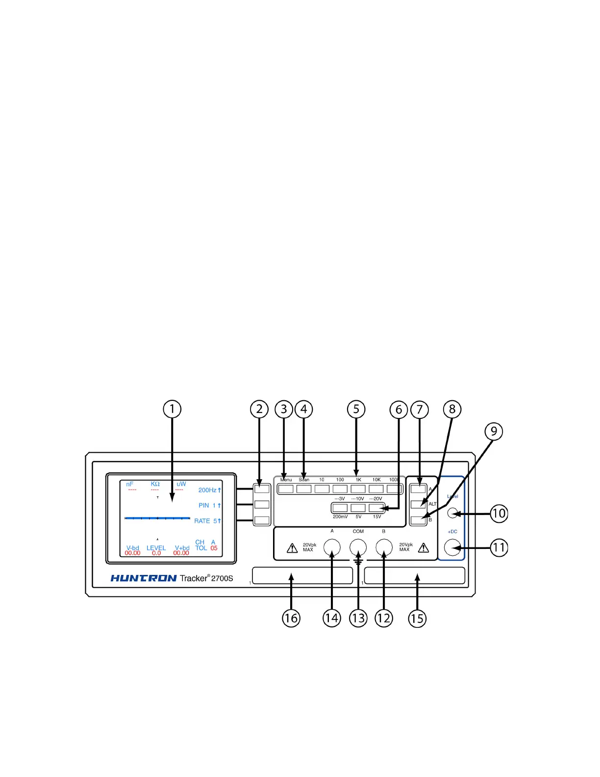
2-6. Front Panel
The front panel of the Tracker 2700 is designed to make function selection easy. All push buttons
are momentary action and have integral LED indicators that show which functions are active.
Refer to Figure 2-1 and Table 2-1 for a detailed description of each item on the front panel.
Figure 2.1 Tracker 2700 (2700S shown) Front Panel with call-outs.