2-
3
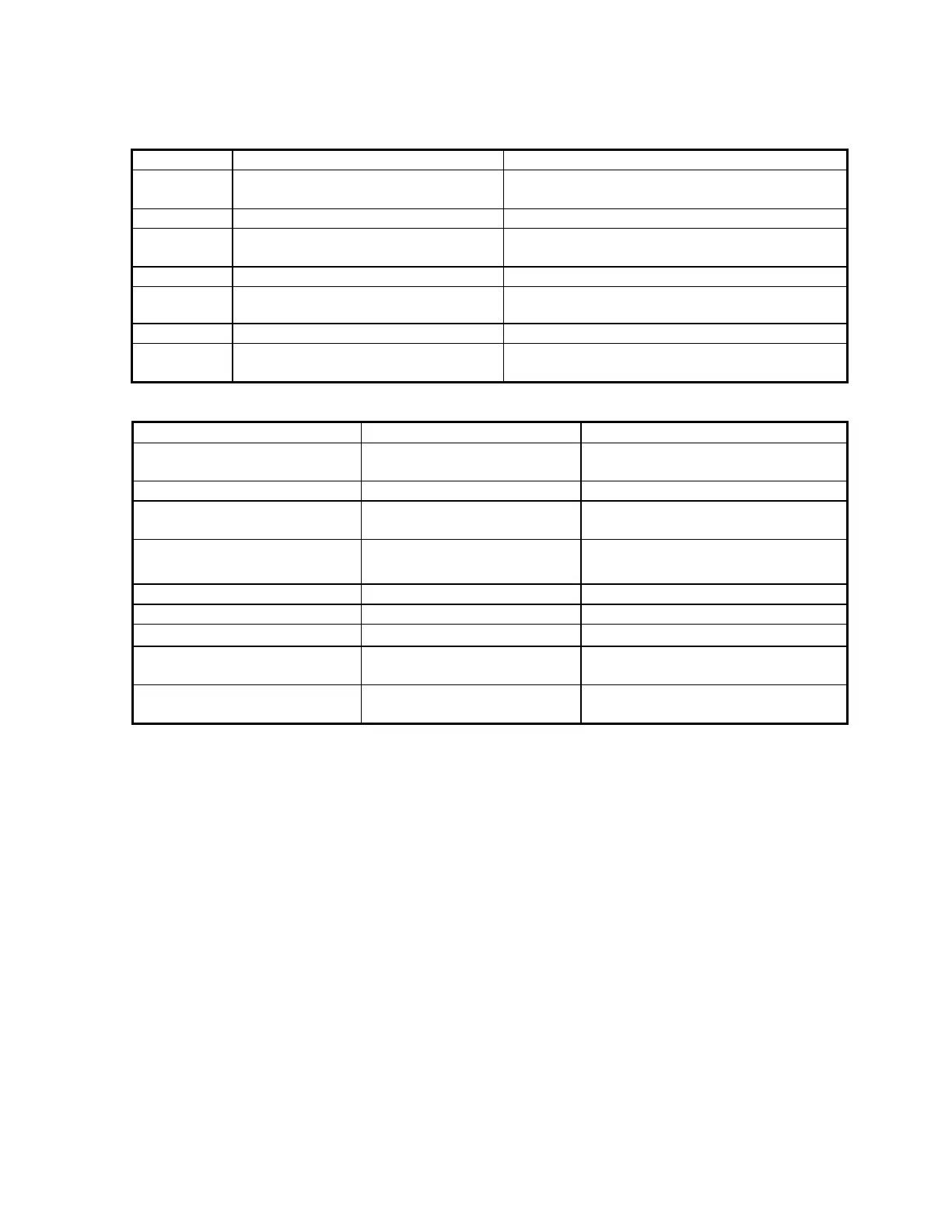
Table 2-1
Front Panel Controls and Connectors
Item No. Name Function
1 Color LCD
Displays signatures, menu items, SigAssist
TM
values, etc.
2 LCD Buttons Used for selection of menu items
3 Menu Button
Displays main menu mode on LCD, stops scan
function
4 Scan Button Cycles through signatures, restarts scan
5 Resistance Selection Buttons
Selects source resistance portion of test
sinewave
6 Voltage Selection Buttons Selects source voltage portion of test sinewave
7
Channel A Button Selects Channel A
Item No. Name Function
8 ALT Button
Selects alternating mode to switch
between Channels
9 Channel B Button Selects Channel B
10
DC Source level
potentiometer Adjusts level of DC Source output
11 DC Source Output Jack
Allows for banana plug connection
to DC Source
12 Channel B banana Jack Connection of Probe
13 Common banana Jack Connection of Clip Lead/Probe
14 Channel A banana Jack Connection of Probe
15
Ch. B 40 pin IDC connector
(2700S only)
Connection of DIP Clip cable
16
Ch. A 40 pin IDC connector
(2700S only)
Connection of DIP Clip cable
 Loading...