2-
4
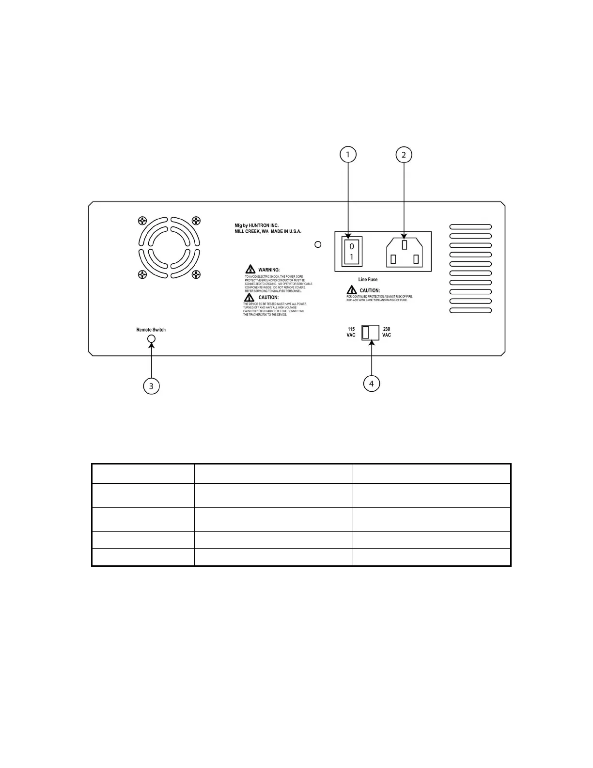
2-7. Back Panel
Secondary controls and connectors are on the back panel. Refer to Figure 2-2 and Table 2-2 for
a detailed description of each item on the back panel.
Figure 2-2. Tracker 2700 Back Panel With Call-outs.
Item No. Name Function
1 Power Switch
Power Off/On for
Tracker 2700
2 Power Cord Connector
Power connection for any CEE-22
power cord
3 Footswitch Connector External control switch
4 Voltage Switch Configures Voltage Supply
Table 2-2. Tracker 2700 Back Panel Connections.