2-
9
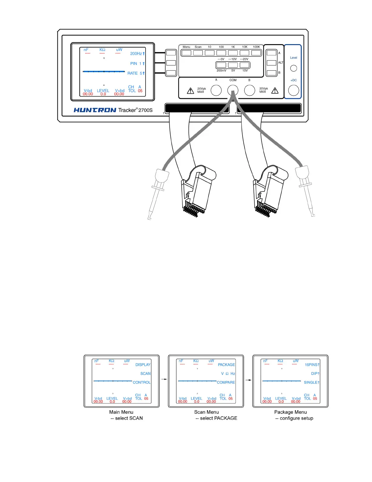
Figure 2-6. Typical 2700S setup with DIP clips
Using the scanning capabilities of the Tracker 2700S is very easy. It is possible to scan using one
channel or both and also make signature comparisons between channel A and channel B.
To scan a component using the front panel cable interface, the package type and number of pins
must first be configured. For more information on the Tracker 2700 menu structure, see section 4
of this manual. Connect an IC cable and clip from each Tracker channel to ICs on side-by side
boards. Connect a Common lead to a common connection such as ground on each board.
Press the Menu button to display the Main menu (first image in figure 2-7). Select SCAN from the
Main menu to display the SCAN menu (second image in figure 2-7). Select PACKAGE from the
Scan menu to display the Package menu (third image in figure 2-7). Use the corresponding LCD
buttons to configure the number of pins, package type (DIP, SIP, BOTH or FRONT) and the scan
mode (SINGLE or LOOP).
Figure 2-7. Scan component configuration
 Loading...