2-
10
Press the menu button until the power-up menu is reached (the signature will become live at this
point). The pins can be manually scanned by pressing the LCD button corresponding with PIN
00↑. The signature for each pin will be displayed on the LCD. Press A to view only channel A, B
to view only channel B or press the ALT button to view signatures on channel A and channel B.
To scan without having to increment the PIN button on the power-up menu, press the Scan
button and the 2700S will step through the pins automatically. Press the Scan button again to
stop the scanning. By default, selecting the Scan button will test each pin in each 2700 resistance
range before stepping to the next pin. To change which range parameter (voltage, resistance or
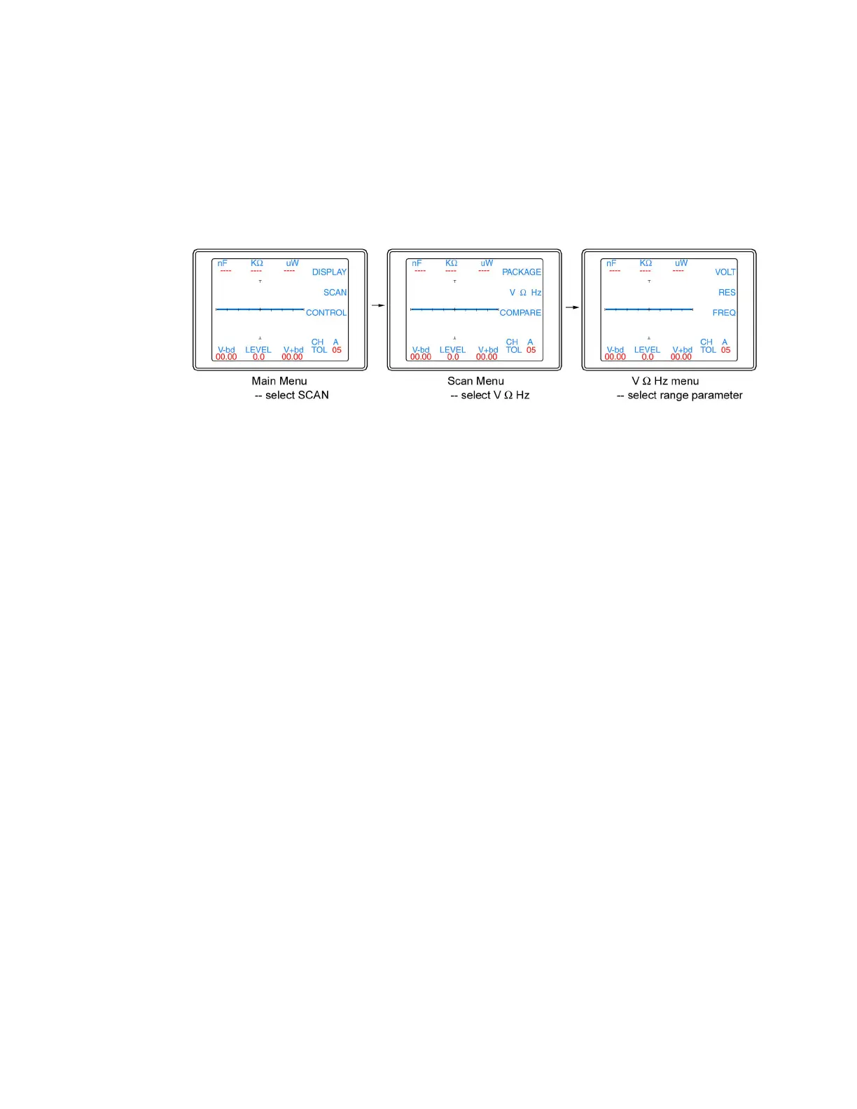
frequency) is incremented during scanning refer to figure 2-8.
Figure 2-8. Selecting range parameter used while scanning
From the V Ω Hz menu, select VOLT for the 2700 voltage to be incremented while scanning,
select RES for the 2700 resistance to be incremented while scanning or select FREQ for the
2700 frequency to be incremented while scanning. Deselect all of the buttons and the 2700S will
scan only in the currently selected range. Press the Menu button until the power-up menu is
reach (the signature will become live at this point). Pressing the Scan button will now scan
through the component pins using the range parameter selected in the Scan / V Ω Hz menu.
The Tracker 2700 can also make signature comparisons and indicate the comparison results on
the LCD as PASSED or FAILED. To set the 2700 to Compare mode, refer to figure 2-9.
 Loading...