3-
2
3-2. Basics Of TSA - How It Works
Here's how TSA and power-off testing works:
The Tracker 2700 outputs a precision current-limited AC sine wave signal to a component and
displays the resulting current flow, voltage drop and any phase shift on the internal LCD’s display.
The current flow causes a vertical trace deflection on the display, while the voltage across the
component causes a horizontal trace deflection. This resultant trace on the display is called a
Tracker signature.
Understanding the Tracker 2700's basic core circuit is the key to understanding how Tracker
signatures respond to different types of components. Since the induced current is a function of
the impedance of the circuit, the Tracker signature displayed can be thought of as a visual
representation of Ohm’s Law,
V = IR where V = voltage, I = current and R = resistance
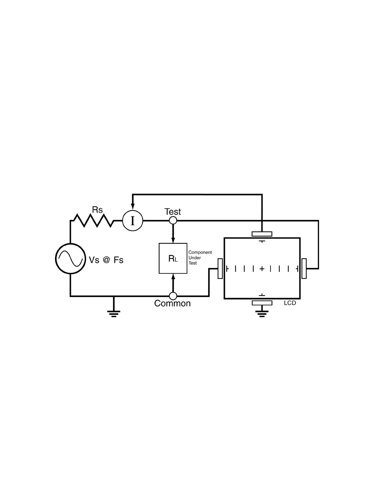
The next figure shows a simplified diagram of the Tracker’s core circuit. The sine wave generator
is the test signal source and is connected to a resistor voltage divider made up of R
s
and R
L
. The
load impedance, R
L
, is the impedance of the component under test. R
L
is in series with the
Tracker 2700's internal or source impedance R
s
. Because R
s
is constant, both the voltage across
the component under test and the current through it is a sole function of R
L
.
Figure 3-2. Tracker
2700 Core Circuit Block Diagram
R
s
= Source Resistance, V
s
= Source Voltage, R
L
= Load Resistance, F
s
=
Source Frequency
Each test signal or range has three parameters: source voltage V
s
, resistance R
s
and source
frequency F
s
. When using TSA for troubleshooting, the objective is to select the range that will
display the most descriptive Tracker signature information. The Tracker 2700 can readily
accomplish this by changing the proper range parameter. The source voltage V
s
of the test signal
can be used to enhance or disregard semiconductor switching and avalanche characteristics. The
F
s
or frequency of the test signal source can be used to enhance or disregard the reactive factor
(capacitance or inductance) of a component or circuit node.
3-3. Horizontal Axis
 Loading...